(313e) The Effect of Impeller Pumping Direction and Impeller Spacing on Fermenter Performance
AIChE Annual Meeting
2020
2020 Virtual AIChE Annual Meeting
North American Mixing Forum
Mixing in Gas-Liquid and Liquid-Liquid Multiphase Systems
Thursday, November 19, 2020 - 9:00am to 9:15am
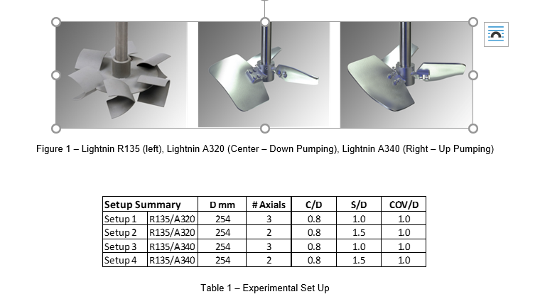
In this work, oxygen mass transfer performance, gas hold up and blend times will be compared between a hybrid system with down pumping impellers versus a hybrid system with up pumping impellers operating under the same conditions (liquid volume, gas rate, gassed power per volume). Lightnin’s R135 hyperbolic radial impeller is used as the lower gas dispersing impeller and Lightnin’s A320 / A340 high solidity axial impellers will be used as the upper impellers (A320 is down pumping and A340 is up pumping). The test vessel is 0.6 m in diameter x 1.22 m liquid level (ungassed liquid volume is equal to 340 liters). Water is used as the liquid and air is used as the gas. The sparge type is a ring sparge placed at the bottom of the vessel below the R135 gas dispersing impeller.
Four impeller geometries are compared as shown in Table 1. C/D represents the impeller off bottom distance versus impeller diameter ratio, S/D represents the impeller spacing distance versus impeller diameter ratio and COV/D represents the liquid coverage distance over the uppermost impeller versus the impeller diameter ratio. For each geometry, oxygen mass transfer (specifically kLa), blend time and gas hold up data will be presented over a range of gassed power per volumes (2.0 to 4.0 kW/m3) and a range of volumetric gas rates (1.0 to 2.0 VVM). Speed and torque are measured using an optical tachometer and a strain gauge torque cell on the drive output shaft. Mass transfer coefficient is determined by applying the batch kLa method (Gigas and Post 1998), which provides insight into whether the impeller geometry has a strong effect on mass transfer coefficient. Blend time comparisons are determined using an acid/base reaction, thus a visual comparison.