(98g) Simulation and Uncertainty Quantification of a Cryogenic Carbon Capture System for Cement Industry
AIChE Annual Meeting
2023
2023 AIChE Annual Meeting
Sustainable Engineering Forum
CO2 Capture for Industrial Point Sources
Sunday, November 5, 2023 - 5:18pm to 5:36pm
This work presents simulation of a cryogenic carbon capture system applied to industrial CO2 emission point sources, particularly from cement plants. A vapor-solid equilibrium model is regressed against experimental flue gas data publicly available in literature at cryogenic conditions, and a 90% capture base case desublimation model is developed. The desublimation model is implemented in Aspen Plus as a 10-stage desublimation column composed of 10 Gibbs reactors in series. Stage outlet temperatures and contact liquid delivery flows to each stage are optimized to maximize the produced slurry temperature at the specified capture level. The cryogenic capture process consists of a direct contact liquid desublimation column, product recovery and heat integration in multi-stream heat exchangers with an external natural gas cooling loop design to take advantage of recirculating refrigerant streams, auto-refrigeration between hot and cold CO2 streams, and multi-stream heat exchangers to streamline heat integration in the process [Jensen, 2015]. This study investigates the main multi-stream heat exchanger for feed cooling against cold product streams and warm LNG. Additional multi-stream heat exchangers for LNG cooling against a natural gas refrigerant loop to achieve cryogenic temperatures and contact liquid/CF4 refrigerant cooling against cold LNG are studied as well.
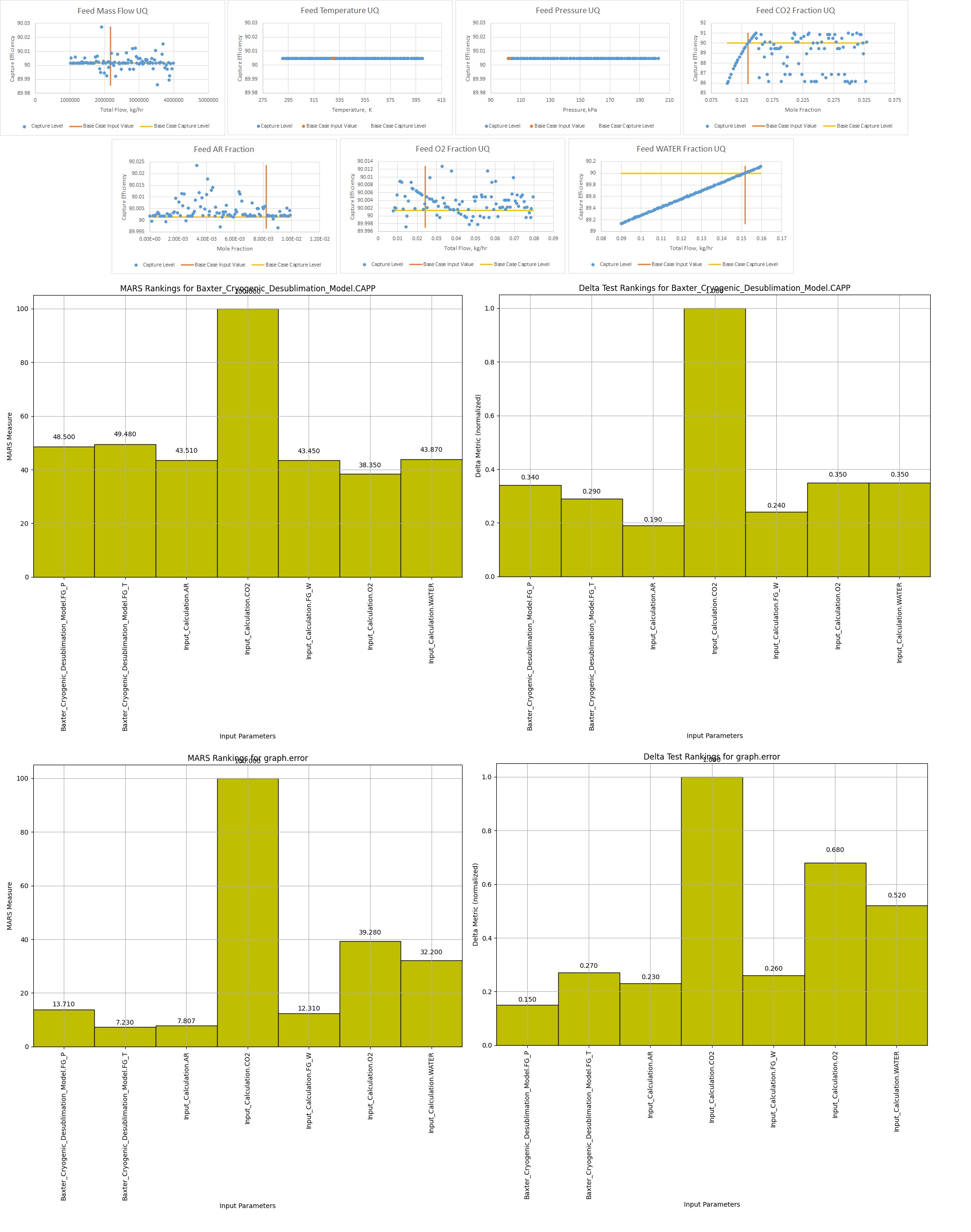
This work leverages the open-source Carbon Capture Simulation Initiative’s (CCSI) toolset (https://github.com/CCSI-Toolset), regression capabilities within Microsoft Excel, and process models in Aspen Plus. Specifically, the cryogenic capture model is integrated with the Framework for Optimization, Uncertainty Quantification, and Surrogates (FOQUS) to assess model robustness and perform uncertainty quantification [Miller et al., 2016]. Sensitivity analysis is performed on capture efficiency and energy requirements as a function of feed state variables and process conditions, such as inlet compositions (notably carbon and water content) flue gas temperature and pressure, to capture the high variability of produced flue gases from available kiln technologies. Column temperature and flow profiles at 90-99.5% capture, the impact of contact liquid temperature on capture efficiency, and contamination of contact liquid in process streams are quantified. In addition, heat integration uncertainty and co-benefit potential for the removal of SOx, NOx, acid gas and mercury are explored. The results show capture efficiency and energy requirements as a function of feed gas state variables including pollutant impurities, and demonstrate contact liquid temperatures required to achieve 90-99.5% capture from 14-33% CO2 in wet flue gas. Heat integration is assessed for uncertainty in filtration efficiency, heat transfer efficiency and changes in ambient temperature and pressure.
The authors graciously acknowledge funding from the U.S. Department of Energy, Office of Fossil Energy and Carbon Management, through the Carbon Capture Program.
References
EPA. Inventory of U.S. Greenhouse Gas Emissions and Sinks: 1990-2019- Chapter 4. Industrial Processes and Product Use, 2021. https://www.epa.gov/ghgemissions/draft-inventory-us-greenhouse-gas-emissions-and-sinks-1990-2019. [Accessed Mar. 27, 2023]
Hasan, M.F., Baliban, R.C., Elia, J.A. and Floudas, C.A., 2012. Modeling, simulation, and optimization of postcombustion CO2 capture for variable feed concentration and flow rate. 1. Chemical absorption and membrane processes. Industrial & engineering chemistry research, 51(48), pp.15642-15664.
IEA. Technology Roadmap – Low-Carbon Transition in the Cement Industry: Foldout, 2018, https://webstore.iea.org/technology-roadmap-low-carbon-transition-in-the-cement-industry-foldout. [Accessed Mar. 27, 2023]
Jensen, Mark, "Energy Process Enabled by Cryogenic Carbon Capture" (2015). Theses and Dissertations.
Miller, D. C., Agarwal D. A., Bhattacharyya D., Boverhof J., Cheah Y-W., Chen Y., et al. (2016). Innovative computational tools and models for the design, optimization, and control of carbon capture processes. 26th European Symposium on Computer Aided Process Engineering – ESCAPE 26. 2391-2396
Nasrifar, K., Moshfeghian, M. (2022). Thermodynamics of carbon dioxide mixtures at cryogenic conditions. Cryogenics 121 103404.
Voldsund, M., Gardarsdottir, S.O., De Lena, E., Pérez-Calvo, J.F., Jamali, A., Berstad, D., Fu, C., Romano, M., Roussanaly, S., Anantharaman, R. and Hoppe, H., 2019. Comparison of technologies for CO2 capture from cement production—Part 1: Technical evaluation. Energies, 12(3), p.559.
Disclaimer: This project was funded by the Department of Energy, National Energy Technology Laboratory an agency of the United States Government, through a support contract. Neither the United States Government nor any agency thereof, nor any of its employees, nor the support contractor, nor any of their employees, makes any warranty, expressor implied, or assumes any legal liability or responsibility for the accuracy, completeness, or usefulness of any information, apparatus, product, or process disclosed, or represents that its use would not infringe privately owned rights. Reference herein to any specific commercial product, process, or service by trade name, trademark, manufacturer, or otherwise does not necessarily constitute or imply its endorsement, recommendation, or favoring by the United States Government or any agency thereof. The views and opinions of authors expressed herein do not necessarily state or reflect those of the United States Government or any agency thereof.