
Introduction
Limited world reserves of liquid fuel as well as the general trend to reduce atmospheric contamination pose many challenges for producers of heat energy. These challenges include increasing fuel combustion efficiency and at the same time reducing emissions. Solution to these problems resides in continuously improving the design of burners and the technology of liquid fuel combustion.
Review of recent studies and publications.
The most promising method of atomizing liquid fuel is using dedicated nozzle cavitators that ensure continuity disruption and improve the dispersion of liquid fuel [1]. Cavitation bubbles and cavity pockets are formed in sites where fluid pressure is lower than the critical one [2, 3 and 4].
Objective.
The theoretical investigations of processes in cavitation nozzles are based on mathematical modelling of fluid flow in intricate channels. The numerical solutions were found using the R-functions method [9]. Different channel flow conditions were investigated with the POLE software package developed under supervision of the late Academician V.L. Rvachev in the Department for Applied Mathematics and Computational Methods [6] in our laboratory. In the Pole software system the R-function method with variation methods (Ritz method, Bubnov-Galerkin method, least squares method) are used for boundary value problems solving. Flow patterns in intricate channels were obtained using the POLE software (Fig. 1.) [6].

Fig. 1. Flow functions in channels
Designs of cavitation devices were obtained based on investigations (Fig. 2.).
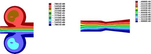
Fig. 2. Cavitation nozzle model
Figure 3 depicts the cavitation nozzle. The flowing part of the nozzle is an axisymmetric channel whose inlet has convergent tube 2 and 4, and the outlet has diffuser 5. The toroidal vortex-mixing chamber 6 is located in the midsection of the channel (Fig. 3). Because rarefaction occurs in chamber 6 during fluid flow in the channel, the second fuel component is sucked in via ejection orifices 8 from auxiliary annular chamber 7. Ejection channels 8 communicate with the rarefaction zone of toroidal chamber 6. The ejected flow sucked in from chamber 7, is separated into m individual orthogonal flows. Each of the m flows is subject to torsion moments created by the shape of the ejection orifices. The number m of ejection channels, and their shape and location in the construction is defined with a technique developed by the authors [5].
In the diffuser channel, cavitation proceeds further; the combustion mixture film is broken up into droplets and water is dissociated partially into Н+ and ОН - ions supporting the molecular dispersion-based reactions of hydrolysis and hydrogenation of high-molecular fractions of organic energy carriers.
During cavitation treatment, the amount of free hydroxyl groups ОН- in water increases, and water acidity can increase to the ultimate value of рН = 14.0. During cavitation, collapsing cavitation bubbles yield important effects. These effects include: significant viscosity reduction; surface energy and tension change; inner energy decrease; the temperatures in the local collapse point rise to critical values of 374 К, at which the latent vaporization heat is practically absent; the water structure changes; intermolecular bond energy is released; water luminescence is observed; electric conductance increases, and chemical activity increases. The chemical compounds in water are activated, since there is practically no pure water, and in the natural state water is a solution of inert gases and different microelements. Reducing the heat of vaporization of cavitated water yields dramatic energy saving, since the heat of vaporization restores its prior value with subsequent condensation of the vapor obtained. The same pertains to reducing surface tension viscosity. This decreases the work expended on formation of vapor bubbles and their subsequent growth [5].
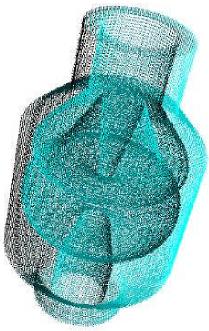
Fig. 3. Cavitation nozzle
Experimental Results
. For cavitation treatment we can use black oil, water, unconditioned hydrocarbons, refinery and coal industry wastes, tank washes, biomass and others.
Three samples of nozzles were used for testing. They were made to the above-described techniques (Fig. 4). The small-size nozzle – inner diameter of the toroidal chamber – 30 mm (external size is ≈3,5 cm in diameter). The medium-size nozzle – inner diameter of the toroidal chamber – 40 mm (external size is ≈5 cm in diameter). The large-size nozzle – inner diameter of the toroidal chamber – 50 mm (external size is ≈7 cm in diameter).
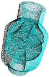
Fig. 4. External view of tested nozzles
Tests were conducted on a certified instrumentation and monitoring gas test bench. Compressed air from the mains was fed to the nozzles, and the atomized liquid was standard automobile diesel fuel.
The tests yielded the following results:
1.When scavenging the nozzles without feeding fuel it was found that, in the investigated air pressure range, there was rarefaction in the fuel channel. Its value increased with growth of initial air pressure at the nozzle inlet (Figs. 5 and 6).
2.Stable atomizing starts at pressures of about (0.3 – 0.5) kgf/cm2.
3.During fuel atomizing two major fractions were distinguished, including, the fine fraction with particle sizes of 5 µm to 10 µm, and a large fraction with particle sizes close to 100 µm. The fine fraction fills the central part of the atomized stream, practically without voids. The large fraction is distributed over the stream periphery and it is made up of droplets formed during disintegration of the film of the liquid phase, which flows with low velocity over the walls of the nozzle outlet port and disintegrates under action of the inner part of the stream flowing out with high velocity.
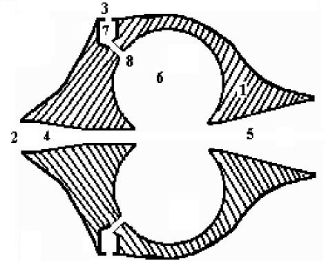
Fig. 5. Rarefaction in the fuel channel vs. nozzle inlet air pressure
1 – small-size nozzle; 2 – medium-size nozzle; 3 – large-size nozzle;
Pinlet – air pressure in inlet of the nozzles; Pt – pressure in toroidal vortex mixing chamber

Fig. 6. Air flow rate vs. Nozzle inlet air pressure: – small-size nozzle;
2 – medium-size fornozzle; 3 – large-size nozzle;
Pinlet – air pressure in inlet of the nozzles; G – air volumetric flow rate
To measure the size of the droplets we use the conductometric method and the laser method. The conductometric method is the better method to measure the size of the droplets in local zones, but the laser method is better for integral measurements.
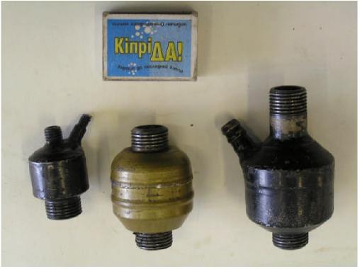
Figure 7. Investigation of spraying dispersion using the laser method
The first run of experiments was conducted as follows: of the 100 % of a mixture of roughly 15 liters, 20 % accounted for black oil and 80 % was virgin petrol. Water in the amount of 25 % of that of black oil was added to the mixture. Batch refinement was conducted upon reaching the temperature of 80 ºС, and the mixture density was 0.837175 kg/m3. The experimental data are given in Table 1.
Table 1. Experimental results of thermal draw refinement of the treated mixture
|
I.c.
|
93 ºС
|
|
10 %
|
120 ºС
|
|
20 %
|
137 ºС
|
|
30 %
|
154 ºС
|
|
40 %
|
175 ºС
|
|
50 %
|
209 ºС
|
|
60 %
|
251 ºС
|
|
70 %
|
314 ºС
|
|
80 %
|
335 ºС
|
|
90 %
|
320 ºС
|
|
F.c.
|
341 ºС
|
|
Yield
|
94 %
|
|
Residue
|
5 %
|
|
Losses
|
1 %
|
|
Temperature in closed crucible – 14 ºС
|
|
The results indicate practically complete batch refinements of black oil in a virgin petrol environment, yielding, mainly, the petrol draw and diesel fuel.
The second run of experiments (Table 2) was refinement of black oil in a diesel fuel environment with a 20 % addition of virgin petrol.
Table 2. Experimental results of draw refinement
|
Washout after refinement
|
Initial
|
|
I.c. 53 ºС
|
I.C. 91 ºС
|
|
10 % 79 ºС
|
10 % 114 ºС
|
|
20 % 95 ºС
|
20 % 131 ºС
|
|
30 % 108 ºС
|
30 % 149 ºС
|
|
40 % 131 ºС
|
40 % 166 ºС
|
|
50 % 187 ºС
|
50 % 214 ºС
|
|
60 % 266 ºС
|
60 % 278 ºС
|
|
70 % 330 ºС
|
70 % 295 ºС
|
|
82 % 358 ºС
|
82 % 294 ºС (initiation of coking)
|
|
F.c. 358 ºС
|
Ρ204=0.7550 g/cm3
|
|
Yield 90 %
|
Flash temperature in closed crucible – 18 ºС
|
|
ρ=0.763 g/cm3
|
Water – 0.018 %
|
|
Flash temperature in closed crucible – 22.5 ºС
|
In spite of refining black oil mainly in diesel fuel, more than 25 % of the black oil passed to the distillate draw from the initial 35 % of black oil.
This set up was also used to study ACLF, comprising the bio mud with a moisture content of 80 % and grade M100 black oil. The fuel obtained was combusted in a firing test bench, including the developed nozzles [9]. The investigations demonstrate that the ACLF (20 % of bio mud and 80 % of M100 black oil) is close in fuel quality to M100 black oil.

Fig. 8. Firing ACLF with a nozzle
Conclusions.
The studies conducted have shown that to create and effectively combust liquid fuel new fluid cavitation technologies are required. It is necessary to use nozzles-cavitators as atomizers during combustion. They do not require special conditions, i.e. heating. It was shown that, by achieving conditions of well-developed bubble cavitation, it is possible to improve atomizing quality and significantly change the chemical composition of combusted fuel mixtures.
Presenter(s)
Once the content has been viewed and you have attested to it, you will be able to download and print a certificate for PDH credits.
If you have already viewed this content,
please click here
to login.