
Follow this guide to keep your combustion and air pollution control equipment running at full capacity.
Troubleshooting is an integral part of keeping any plant in the chemical process industries (CPI) functional. It requires fieldwork and typically involves working and communicating with facility personnel, conducting investigations, gathering test data, and performing calculations. Troubleshooters are often brought into a facility when problems must be solved quickly, such as during a startup or shutdown.
This article offers basic guidance on how to get to the root cause of a problem when troubleshooting combustion and air pollution control equipment, and discusses some techniques that will help you determine a solution quickly and efficiently. It also suggests the tools and equipment that every troubleshooter should have in their toolbox.
The science of troubleshooting. Troubleshooting can be described as the process of breaking a problem in half, and breaking it in half again, until it can be solved. In any given troubleshooting scenario, the underlying problem may be caused by a multitude of possibilities. The goal is to reduce the number of possibilities in order to determine a root cause and find a solution. One simple troubleshooting example is a car that cranks but will not start. A shot of ether or other starting fluid into the engine air intake will quickly tell you if the fault is due to a lack of fuel supply. If it does not start with a shot of extremely flammable starting fluid, clearly it must be an issue with the ignition.

▲Figure 1. This schematic illustrates the concept of breaking the problem in half. Here, we use the technique to find a burned-out bulb in a 100-bulb series-wired string of holiday lights.
Large systems require more troubleshooting steps to isolate the problem and find the fault than smaller systems. If you have ever experienced a series-wired string of holiday bulbs that stop working, you know that the shorter the series is, the quicker you can find the bad bulb. However, let’s imagine that you need to find one bad bulb within a string of 100 lights (Figure 1). On average, checking each bulb from 1 to 100 would locate the bad one after testing 50 bulbs, but in the worst case, this method would take 99 tries before the bad one is found. By breaking the problem in half repeatedly, as shown in Figure 1, you can find the bad bulb in only seven steps. This same logic can be applied to many other situations, such as leak detection in large piping systems, as well as troubleshooting series-wired safety switches and glass joints in stack test gear.
Safety first
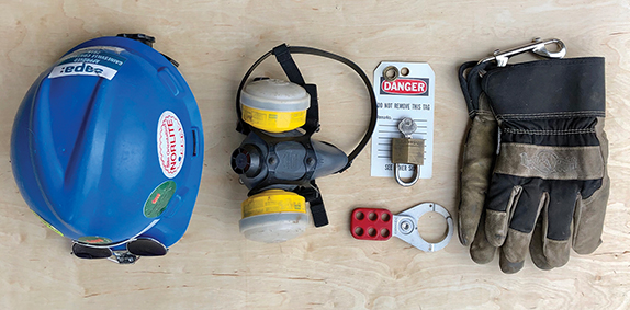
▲Figure 2. Important safety gear that any troubleshooter should have on hand include (from left to right): hardhat, dual-cylinder air-purifying respirator, lockout/tagout gear, and leather-faced insulated gloves.
As a troubleshooter, it is wise to carry your own safety gear. This will help you avoid the hassle of borrowing gear (which is often ill-fitting) on-site. I recommend bringing your own hardhat, dual-cylinder air purifying respirator, lockout/tagout gear, and leather-faced insulated gloves (Figure 2). I prefer gloves with a hook or ring to hang on a belt loop so they do not get lost on job sites. Not shown in Figure 2, but normally required, are steel-toed boots and safety glasses or side shields.
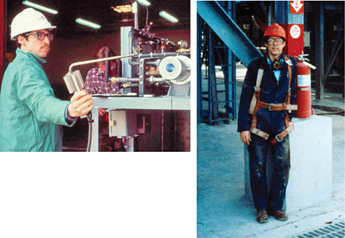
▲Figure 3. A flame-resistant jacket for burner testing (left) and full harness for confined-space entry (right) are critical safety gear when troubleshooting combustion and air pollution control equipment.
Proper hot-work clothing and a harness for confined-space entry work are also critical safety gear (Figure 3). On the left side of Figure 3, I am wearing a flame-resistant cotton jacket while testing an oxygen burner. When you are working around combustion or hot equipment, long sleeves and all-cotton outerwear are critical because synthetics can melt, stick, and burn when exposed to heat. Likewise, splash protection gear is required for work on liquid scrubber systems with hot water and caustic solutions. On the right side of Figure 3, the harness I am wearing was used to retrieve me after I inspected a 3,500-hp dual-entry induced-draft (ID) fan on a pulp mill boiler.
Troubleshooting: Before, during, and after
You can save time by taking the following steps before you head to the job site:
- review available piping and instrumentation diagrams (P&IDs), standard operating procedures (SOPs), cut sheets, and vendor information
- review available data from stack tests, event logs, etc.
- check and pack your test gear; charge or change batteries.
While you are on-site and after you leave, take the following steps:
- have an arrival meeting on-site to hear the clients’ stories and their goals
- have a debriefing session before leaving the site every day
- write up notes on-site, after hours, or at the start of the day to stay current and focused
- take time out to think — be aware that things may look simpler the next morning, or even after lunch
- call original equipment manufacturer (OEM) vendors and access installation and operating instructions online
- collect data and perform calculations to cross-check against the design
- use field instruments to gather data and to cross-check and verify process data as needed
- follow up with a trip report that includes findings and recommendations, and as-found and as-left settings and conditions.
Useful tools
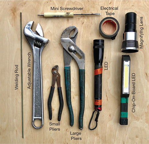
▲Figure 4. These hand tools belong in any troubleshooter’s gear case.
Getting the data you need to troubleshoot may be easier in newer, well-instrumented plants with data historians than in older plants with little instrumentation. However, key data can be lacking even within newer plants. In many situations, having the right tools will help you collect the data you need (Figure 4). For example, a welding rod, which is readily available underfoot on most job sites, can come in handy to clear out ports and plugged instrument lines, allowing you to more easily take measurements.
In my gear case, I carry an adjustable wrench and both large and small tongue-and-groove slip-joint (e.g., Channellock) pliers (Figure 4). The curved jaws of the large pliers are useful for minor piping work. I typically carry two lights: a focusable LED flashlight and a brilliant chip-on-board (COB) LED flashlight. The COB LED is useful for lighting the inside of dark equipment when taking photos. I also have a 50:1 magnifying lens, electrical tape, and a small screwdriver on hand. The screwdriver is needed to swap batteries on test equipment. It is also a good idea to carry two spare batteries with you because you will need them sooner or later.
A cellphone camera (not shown) is a very powerful tool. Many times, you can avoid entering equipment if you can use your camera to do the work for you. You can even take photos of a control panel graphic to record process data. Finally, a Swiss Army knife or other multitool can be useful. See Ref. 1 for more information on tools in general.
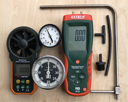
▲Figure 5. Instruments for measuring flow and pressure include (from left to right): velometer, compound gauge (top), mechanical tachometer (bottom), digital manometer, adapter, plastic tee and hose, and stainless steel pitot tube.
Flow testing gear. Throughout the troubleshooting process, you may need to take quick flow and pressure measurements. Some common test gear that I use to take these readings includes (Figure 5):
- a velometer, or vane-type velocity meter, which can measure air flows into grills, filters, fans, and blowers
- a compound gauge that can measure pressures from 0 psia (30 in. of Hg vacuum) to 30 psig
- a mechanical tachometer to measure the speed of a fan or pump controlled by a variable frequency drive (VFD), which can be checked against fan and pump curves
- a digital manometer, which is useful for readings of ±60 in. w.c. (~2 psig) — these measurements can be taken as single-port or as ΔP readings
- male pipe-thread-to-barbed-fitting adapters, plastic tee, and hose, which are handy for hooking up gauges and meters to various fans, gas trains, and gas orifice meters. They are also useful for checking pressure drop across scrubber packing, demisters, and baghouse bags
- a stainless steel pitot tube.
The pitot tube measures total pressure and static pressure, and the difference between these two measurements is velocity pressure. Remember that velocity and mass flow can be easily calculated if you know the velocity pressure, gas or liquid temperature, and the internal diameter of the associated pipe or duct.
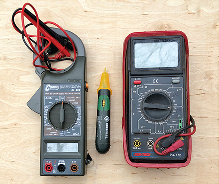
▲Figure 6. In the field, it is often useful to take electrical property measurements using instruments such as an amprobe multimeter (left), noncontact hot-wire tester (center), and multimeter that accepts a Type K thermocouple input (right).
Electrical test instruments. Even with good onsite support, a missing instrument can cause delay. I recommend carrying a few tools to test electrical properties, such as a clamp-on amprobe with built in multimeter (Figure 6, left) and a noncontact hot-wire sensor (Figure 6, center). To verify that the hot-wire sensor is working before you try to check plant wiring, run the tip through your hair so that the static electricity generated will trigger it. I also recommend a multimeter that can accept a Type K thermocouple (TC) input to read temperatures (Figure 6, right). Both multimeters can check resistance and continuity to identify open and shorted lines, as well as direct current (DC) or alternating current (AC) voltage and milliamps. With voltage and amperage readings in hand, you can calculate motor power on pumps and fans to check against the equipment’s operating curves.
Temperature and emissions testing tools
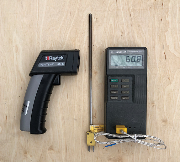
▲Figure 7. These common instruments can be used to measure temperature in the field (from left to right): infrared (IR) noncontact thermometer, Type K thermocouple (TC), and dual-channel field TC readout.
Figure 7 shows some of the instruments I use the most to measure temperature. On the left is an infrared (IR) noncontact thermometer. It can read surface temperature at a distance, such as shell temperatures, feed and product temperatures, and skin temperatures of uninsulated liquid lines that are close to the liquid temperature. IR instruments are typically set for an emissivity factor of 0.85, but stainless steel and other surfaces may have much lower emissivity, which will cause the instrument to read low. Use painter’s tape or electrical tape, or spray black matte paint on the target area, to raise the target’s emissivity. Alternatively, place a lightweight field TC on the target and cover it with an insulating pad, weigh down the insulating pad until the reading is steady, and then either change the emissivity on the IR thermometer to match or use the offset to correct IR readings.
In the center of Figure 7 is a Type K TC. Note the yellow tag attached to the TC near the plug. All TCs are so marked by vendors with their TC type and model number. On the right is a dual-channel TC readout that can provide ΔT readings and hold high and low temperatures in its memory.
In a few unique cases, the best way to estimate temperature is by sight. For example, within an iron or steel furnace (such as a bar reheat furnace), a lighter steel color indicates a higher temperature (Table 1) (2).
| Table 1. Different flame colors within an iron or steel furnace correspond to different temperatures. Source: (2). | |
| Flame Color | Temperature, ºF |
| Dark Red | 1,050 |
| Dark Cherry Red | 1,175 |
| Cherry Red | 1,375 |
| Orange | 1,650 |
| Light Orange | 1,725 |
| Yellow | 1,825 |
| White | 2,200 |
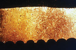
▲Figure 8. Sawdust and wood chips are fed to a furnace at a paper mill. The view through the sightglass into the spreader-stoker indicates the furnace temperature. The yellow and white areas are hotter, while the darker spots are cooler wood particles.
Figure 8 shows the view into a 450 million Btu/hr spreader-stoker that fed hog fuel (sawdust and chips) to a bark boiler furnace at a paper mill. Based on Table 1, the yellow color of the furnace and flame tells us that the furnace is running at less than 2,000°F. The darker spots in Figure 8 are cooler, larger wet suspended wood particles.
Table 1 can also be used as a guide to estimate the temperature of refractory surfaces, but keep in mind that color depends on a material’s emissivity. Some surfaces will show less light or color at the same temperature as steel. In general, refractory material inside a shell fired at 1,800°F will be orange to light-orange.
Combustion testing. On startup of a combustion system (and prior to any compliance testing), a combustion analyzer should be used to ensure that the system is functioning properly. For example, a high CO reading on an oxidizer might also signal poor volatile organic compound (VOC) destruction, a fouled burner, a high-reading TC or incorrect type of TC (both resulting in a chamber temperature that is too low), or a fouled nozzle if the system is liquid-fueled.

▲Figure 9. A troubleshooter may use various handheld instruments such as these to test stack emissions.
Figure 9 shows three combustion analyzers that I use in my work. The analyzer on the left provides CO and O2 data. The device in the center provides CO, CO2, H2, O2, CH4, C2H2, and CnHm readings simultaneously, and also calculates the gas heating value and N2 balance automatically when monitoring rich gases. The analyzer on the right provides CO, O2, NOx, and SO2 data.
The analyzers on the left and right use chemical cells that must be replaced every two or three years. They also choke and exceed the range on the display at high CO levels. This can be a problem during start up and air/fuel ratio tuning, as returning them to service takes time and requires purging with fresh air. The instrument in the center contains a chemical cell for O2 measurement; for the remaining gases, it employs nondispersive IR (NDIR) technology and does not choke at high CO levels. While its major application is for gasifiers and other rich-gas producers, it can also analyze lean stack gases.
These analyzers come in handy during startup to make sure the excess air level is on target. You can use O2 or CO2 readings to tune the air-to-fuel ratio. Too little excess air can burn up equipment and ignite feedstocks such as wood chips in a rotary dryer. Too much excess air reduces fuel economy. CO should also be checked and, in general, should be under 100 parts per million (ppm) in most combustion systems. Systems that run with furnace temperatures above 1,750°F frequently show CO levels close to zero. VOCs, NOx, and SO2 readings may also be required for emission compliance. High readings of any of these may indicate a problem with the pollution control system. For example, high SO2 may simply require a slightly higher pH, necessitating higher lime or caustic concentration in the scrubber liquor to meet the limit. Or, it may require swapping out the scrubber liquor spray nozzle or adding more column packing.
Valve and spray nozzle troubleshooting
Valves. Some obvious problems can arise from using the wrong type of valve (e.g., using a gate valve for throttling), undersizing or oversizing valves, or forgetting that valve percent open does not equal percent flow for uncharacterized valves. Many control valves are sized at half or three-quarters of the line size based on their flow coefficient. An undersized control valve will deliver less fluid than required. An oversized valve will provide poor control — if the valve is operating nearly closed, a small change in valve position will cause a large change in flow.
Aside from simple problems, many other problems can arise, such as:
- ball valves with snapped shafts that are hidden
- closed ball valves in drained lines that have cracked due to trapped water freezing inside the ball
- hidden snapped shafts on nonrising-stem valves (which may appear open when shut)
- debris in the valve body that prevents full closure (especially in gate valves mounted with the handle up)
- debris in the valve bonnet that prevents full opening (especially in gate valves mounted with the handle down)
- seal surfaces that are scored (e.g., on ball valves), corroded, or eroded, causing leaks
- solenoid valves installed backwards
- valve operator linkages that are slipping
- stem packing that is leaking.
In general, pipe surface (or fluid) temperature and pressure downstream might indicate that a valve is open or leaking when it should be in the off/closed position. Other issues may require valve removal to find out what is wrong.
Spray nozzles. Many air pollution control systems contain spray nozzles in quench towers and SO2/HCl acid gas scrubbers. Spray nozzles are also used to atomize and burn fuel oil and liquid wastes.
Two types of spray nozzles are common: High-pressure hydraulically atomized nozzles produce larger droplets, and air- (or steam)-atomized nozzles produce finer droplets. Many field problems with spray nozzles are caused by improper design. The wrong choice of solid vs. hollow-cone spray pattern, spray angle, droplet size, pressure, upstream filtration, and material of construction will cause problems and necessitate troubleshooting.
The piping that connects a spray nozzle to the air or liquid inlet is called the lance. Lances on heavy-oil burners may require swapping once per shift, whereas others, such as those in scrubber systems, might be swapped once per month. Problems can be avoided at an early stage if sight glasses are added to the furnace or quench chamber to allow examination while in operation. If you find that downtime for troubleshooting and service is excessive, redesign the system to make it easier to inspect and replace the lance. Adding local pressure gauges will also help in troubleshooting and routine observation.
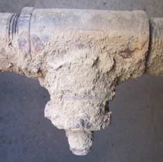
▲Figure 10. Spray nozzles often foul and plug, as has occurred here due to lime fouling.
When troubleshooting spray nozzles, expect that nozzles will foul (Figure 10), plug, erode, burn up, and/or come loose from headers. Remember to perform a bench test to verify the spray angle and pattern before placing any nozzle in service. If drips occur during the bench test, the nozzle may be misassembled or poorly machined. It also helps to have easily detachable couplings and flexible lines, which reduce maintenance time for changing out lance and nozzle assemblies.
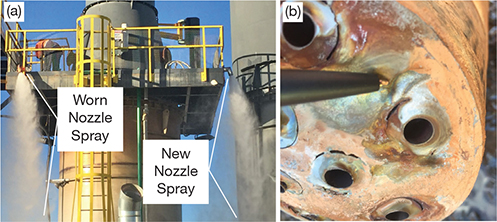
▲Figure 11. (a) We tested the difference between an old spray nozzle and a new nozzle by anchoring them to a high platform and streaming water through the nozzles. There was a noticeable difference between the density of the worn nozzle’s spray and that of the new nozzle’s spray. (b) Closer inspection of the old nozzle indicated cracking and port enlargement due to HCl attack.
Case study: Quench tower nozzle. An 80-ft dry-bottom quench tower reduced gas temperature from 1,800°F to 350°F prior to the dusty gas entering a baghouse. Mud was forming in the bottom of the tower, and the water flowrate was increased to keep the outlet temperature within specification. This pointed to degraded nozzle operation, with larger droplets not evaporating and/or droplets departing from an expected narrow angle and hitting the walls. To troubleshoot the problem, we compared the flow of the old nozzle to that of a newer nozzle (Figure 11a). There was a noticeable difference in the sprays from the worn nozzle and the new nozzle — the old nozzle produced a denser, more opaque spray than the new one. Closer visual examination of the internal-mix, drilled multiport nozzles indicated port enlargement and surface cracking due to HCl attack (Figure 11b). For this application, Hastelloy should have been used rather than Type 316 stainless steel to combat HCl degradation. The solution was to install new nozzles, which reduced water use, and mud formation ceased.
While you cannot always see inside equipment to identify and troubleshoot a problem, you can still visualize what may be happening to fluids and solids. Keep in mind that gases, liquids, and solids all have momentum and continue to travel in one direction, although this is more relevant to liquid droplets and solids than gases.
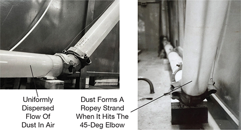
▲Figure 12. This 4-in.-dia. piping system was used for industrial-scale pneumatic conveying testing to demonstrate particle flow. At first, the particles are uniformly distributed throughout the pipe (left). When they hit a 45-deg. elbow, they form a ropey strand (right).
Early in my career, I performed industrial-scale research in clear acrylic equipment, and this trained my eye to visualize such flows. Figure 12 shows photos of my 4-in.-dia. pneumatic conveyer test system made of clear acrylic. Notice that the particles, which are evenly distributed at first, form a ropey strand downstream of a 45-deg. elbow. The following case study shows how this helped me visualize the problem.
Case study: Upshot quench not working well. A plant quenched hot gas from a furnace with an air-atomizing water nozzle. The entering gas was quenched from 1,700°F to 400°F, then exited vertically upward through an elbow to a horizontal duct. The thick-backed elbow was thinning rapidly. One expert believed it was alkali attack. I believed this unlikely, because, in general, steel and alkalis are compatible. I believed that the nozzle was at fault. I proved it without shutting down the system by simply checking the back of the elbow’s surface temperature. It was 100°F, while the duct downstream was over 250°F. This indicated that liquid droplets were hitting the outer elbow wall and evaporating there, rather than quenching the gas in the quench chamber, which had a residence time that was too short. Those droplets hitting the wall absorbed HCl from the upstream process, quickly corroding the metal. A new nozzle and higher atomizing air pressure solved the problem. As a result, elbow surface temperatures returned to above the boiling point.
Combustion system troubleshooting
Combustion systems have the following main components:
- air and fuel trains that provide combustion air and gas, oil, or solid fuel
- a burner that mixes fuel with air, provides a source of ignition, and holds a propagated flame
- a temperature/flow control system for fuel/air input
- a burner management system (BMS) to monitor the flame and provide important startup and safety/shutdown functions.
Burners fire into furnaces and can be small (e.g., small package boilers) or large (e.g., pulverized coal-fired utility boilers). References 3 and 4 provide more background information on burners, combustion, and furnace design. In addition, the National Fire Protection Association (NFPA) publishes codes and standards that cover important design and operation requirements, such as the number of air changes to purge a furnace before light-off to prevent explosions, and the maximum time for pilot ignition.
When troubleshooting burners, the main problems typically relate to hardware (e.g., burner fouling) or controls (e.g., loose or slipping fuel and air valve mechanical linkages, fouled flame monitors, inoperative high temperature limits). The first thing to do during a shutdown inspection is to look at the burner from the inside of the equipment, or pull the burner from the furnace to inspect it. Ensure that the tile (burner block) is intact, not cracked or broken; if it is damaged, repair or replace it. Clear any slag that may have built up on the burner block. If slag builds up quickly, reduce the upstream source of slag, and consider a different burner that pulls less ash back to the base of the flame.
Check for any plugged air tubes or jammed air louvers in the burner body; clean any air tubes and/or lubricate any air louver linkages as needed. Also, check whether louver damage was caused by reverse flow of hot gas. If the intake filters on the combustion air fan are fouled, they need to be cleaned or replaced. It also might be a good idea to consider moving those intakes to a less dusty area.
After addressing these items, several smaller but critical things should be inspected:
- ensure that the gap on the spark plug is correct (if it is too wide, it will not spark, and if it is too narrow, not enough fuel/air will be ignited)
- check the air/fuel mixture on the pilot
- ensure that the series-wired safety devices, such as high- and low-pressure switches on the fuel train, are functional
- validate that the combustion air flow switch is working properly.
Case study: Stack test for NOx emissions. A large high-temperature process system had high NOx emissions. The engineers checked the flow in the stacks to calculate the mass flowrate of NOx emissions in lb/hr. The older line had a large-diameter stack, so the engineers had to use a very long pitot tube to measure flow. (Keep in mind that pitot tube velocity pressure is proportional to the square of velocity.) Velocity pressure readings were in a reasonable range of ~0.35 in. w.c. with hot gas at a velocity of ~40 ft/sec. In a second stack on an identical but newer line, the velocity pressure was barely measureable at ~0.01 in. w.c. A review of both processes showed the same fuel and feed inputs and excess air levels.
Over lunch, the puzzle was solved when we saw an aerial photo on the wall. We noticed the newer line had a much taller stack to aid in dispersion. It was built with a 30% larger diameter and a lower stack velocity of 25 ft/sec. The lower gas velocity had reduced our velocity pressure reading. We had not spotted the difference standing close to the stack on a cramped (and high) platform. We fixed the problem by instead measuring the flow in a smaller duct going to the fan.
Pumps, fans, and other machinery
Many pumps and fans are the centrifugal type, but they vary in design (e.g., forward, backward, radial impellers) depending on application. As many as half of all three-phase powered pumps and fans turn backward on startup. They pump or blow the correct way, but at reduced rates. To check for this, perform a bump start by quickly starting and stopping the motor. If the direction is incorrect, you can fix it by reversing two lead wires or by using the software switch on a VFD.
If a centrifugal fan’s flowrate has been throttled back too far, the fan will operate in an unstable region on its fan curve and surging will occur. In severe cases, a fan will “sneeze” by shooting air out of its intake. This will be evident by rapid oscillation on output pressure gauges.
Positive-displacement pumps and blowers (as well as centrifugal regenerative blowers) that are throttled back too far require a bypass, as they can overheat and lock up. Typically pumps have a check valve on the outlet to prevent backflow, and some have a built-in overpressure bypass.
Case study: Using temperature to troubleshoot a pump problem. A system of three parallel-piped centrifugal pumps supplied water to a quench tower downstream of an incinerator. Temperatures were climbing in the gas phase — indicating lack of water or atomization problems. Using an IR temperature gun, I found that the outlet pipes from the two pumps that were in operation were around 170°F. The third pump was an installed spare, and although the installed spare was switched off and closed by two valves, its inlet and outlet pipes had nearly the same skin temperatures as the operating pump lines. Backflow was occurring, which reduced the output of both running pumps. The backflow was caused by two problems: a failing plastic ball valve and a new stainless steel valve with a nicked ball that prevented full closure. As a fix, the nick was filed off to allow full closure and the plastic valve was replaced.
Case study: Auger drive gearbox. A dioxin-contaminated soil remediation project treated soil in a rotary desorber. The hot product soil, at around 900°F, was transported by a screw auger. The auger gearbox wore out on a monthly basis, causing excessive downtime. Working with the mechanic, I learned that dirt was found in the gearbox oil. Gearboxes have vents, and this gearbox was subjected to hot and cold temperature changes, as well as atmospheric pressure changes. These changes caused the gearbox to take in fine clay from the job site. As a solution, I recommended that they switch to a heavy-duty gearbox with a filter and a bladder that expands and contracts to keep all air out.
Case study: Positive-displacement blower. A 4-in. Schedule 40 pipe with a 3-in. orifice was used to meter air (produced by a 150-hp rotary-lobe positive-displacement blower) to a variety of industrial test equipment. The balance of air that was not used for experiments was vented to the atmosphere by a 4-in. gate valve through a vertical 20-ft pipe, 90-deg. elbow, and short nipple. One morning, the test equipment was not getting the expected flow, but the orifice ΔP reading was high. This made little sense. We broke open the line and found a large, dead crow stuck in the orifice. We fixed the problem (and kept rain out of the system) by adding an additional 45-deg. elbow, a short nipple, and a bird screen to the vent pipe.
This case study proves that sometimes you will need to follow a process upstream to determine the root cause of a problem, and that sometimes a hands-on approach is the best problem-solving method.
Closing thoughts
When troubleshooting, be observant and keep your eyes open. Talk to people, and be sure to listen as well. Be persistent. Break the problem into parts to speed up the work. Take good notes and always write up a trip report. And, consider safety above all.
Literature Cited
- U.S. Navy, “Tools and Their Uses — An Armed Forces Training Manual,” www.maritime.org/doc/pdf/tools.pdf (1992).
- Baumeister, T., et al., eds., “Marks’ Standard Handbook for Mechanical Engineers,” 8th Ed., McGraw-Hill, New York, NY (1979).
- Reed, R., “North American Combustion Handbooks (Volumes I-II),” North American Manufacturing Co., Cleveland, OH, https://combustion.fivesgroup.com/literature/north-american/handbooks.html (1978).
- Trinks, W., et al., “Industrial Furnaces,” 5th Ed., Wiley, Hoboken, NJ (1961).
1

Copyright Permissions
Would you like to reuse content from CEP Magazine? It’s easy to request permission to reuse content. Simply click here to connect instantly to licensing services, where you can choose from a list of options regarding how you would like to reuse the desired content and complete the transaction.