
Several important process control topics don’t receive much, if any, coverage in the traditional chemical engineering curriculum.
Many university process control courses do not adequately prepare chemical engineering graduates for their first jobs in industry. Much of the content of academic process control courses (e.g., Laplace transforms, Bode plots, root locus analyses, Routh/Nyquist stability algorithms) is rarely used in industry, and almost never for batch and discrete processes. Process control topics of major industrial importance, such as programmable logic controllers (PLCs), distributed control systems (DCSs), safety instrumented systems (SISs), and national standards and regulatory considerations, are typically not covered at all (1). This leaves many new graduates unprepared to tackle tasks associated with process monitoring, troubleshooting, and process control.
A major portion of the undergraduate process control course is spent on linear control theory and methods, which are applicable to continuous processes running at or near steady state. Several petrochemical processes fit this mold. However, many manufacturing processes are discrete or time-varying batch processes, which require different considerations than steady-state processes. Batch processes are very common in the chemical process industries (CPI), and include most pharmaceutical and biotech processes, food and beverage processes (including beer production), and specialty chemicals (e.g., soaps and paints) production. Examples of discrete processes include the manufacture of pharmaceutical tablets and automated inspection and packaging of final products.
To close the gap between the needs of industry and the content taught in undergraduate process control courses, companies often need to send new process engineers to vendor and technical society control courses; in most cases, senior employees must spend significant amounts of time training new hires before they become productive.
This article discusses several industrially important process control topics, many of which do not receive much, if any, coverage in the traditional chemical engineering curriculum. The hope is that these topics will be covered in future editions of process control textbooks and future lectures in academic process control courses. The article may help graduating chemical engineers know what to expect when they start their careers in industry.
In many industrial plants, control system equipment has a long life, usually due to the major capital costs, time investment, and lost production incurred by installing replacements. So, new engineers may sometimes discover instrumentation and control equipment that has been in place for more than 20 years. Therefore, this article includes brief references to some of the older technologies that are still in use (2).
Regulations and Standards
The process of specifying, designing, implementing, and operating a process control system involves many well-publicized best practices, some of which are requirements for certain industries. These include:
- NFPA 70, National Electric Code, the benchmark for safe electrical design, installation, and inspection
- current good manufacturing practices (cGMPs) set by the U.S. Food and Drug Administration (FDA) for the pharmaceutical and medical device industries
- standards set by the American National Standards Institute (ANSI), such as the standards for safety instrumented systems (ANSI/ISA-84), alarm management (ANSI/ISA-18.2), batch process control (ANSI/ISA-88), human machine interfaces (ISA-101), and procedural automation (ISA-106)
- reporting requirements in regulations promulgated by the U.S. Occupational Safety and Health Administration (OSHA) concerning safety training and records and the Environmental Protection Agency (EPA) concerning accidental releases of hazardous chemicals to the environment.
When developing new process control systems or supporting existing ones, understand and follow all relevant local, state, and federal regulations and standards. For example, all measurements associated with safety, the environment, or product quality should be identified, monitored, alarmed, and logged so that any incidents that occur can be formally responded to by operators, investigated by a company’s health, safety, and environmental (HSE) and/or quality control groups, and reported to appropriate management and government agencies.
Control system hardware
Figure 1 illustrates a generalized computer-based process automation architecture. Three common options are available for implementing computer-based process control: a personal computer (PC), PLC, or DCS. All are interfaced to process equipment (e.g., sensors and valves) via input/output (I/O) subsystems. PLCs and DCSs usually have access to other computers that support plant operations via a local area network (LAN).
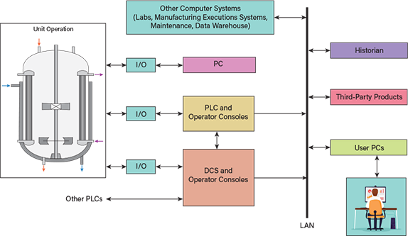
▲Figure 1. Personal computers (PCs), programmable logic controllers (PLCs) and distributed control systems (DCSs) are options for providing process control for a unit operation. These computer-based systems interface to process equipment via input/output (I/O) subsystems. PLCs and DCSs typically interface with other plant computers through a local area network (LAN).
Personal computers. Many university control courses and research labs use low-cost PCs, rather than industrial control systems, for process monitoring and control. While these systems can be useful to teach and implement basic concepts, they lack the industrial hardening, complex functionality, and reliability of industrial control systems. In CPI facilities, control systems are often completely separated from PCs and their networks for cybersecurity reasons. Furthermore, PCs are not typically used for applications involving highly regulated processes that require formal validation, including automated audit trails and electronic signatures.
Programmable logic controllers. PLCs are the primary industrial workhorses for process control. These specialized computers were conceived and developed decades ago as a replacement for mechanical relay sequencing, and they utilize a programming technique called ladder logic. Such systems have evolved to meet most of the requirements for modern industrial plant control systems and also address the limitations of PC systems.
A PLC typically monitors and controls the operations of a machine, a major piece of equipment, or a defined portion of a plant. It has the capacity to monitor and control several hundred devices or control loops. PLCs are especially useful for high-speed operations and discrete control applications, such as motor start/stop controls, mechanical actuators, robotics, and product filling and packaging lines. Modern PLCs are capable of managing large continuous processes, but in large plants they are usually used in combination with DCSs.
The alarm, human machine interface (HMI), and historian portions of a PLC-controlled process often reside in separate computers from the PLC itself. Often, the many PLCs and HMIs within a plant were designed by different vendors or engineering teams. Therefore, there can be many inconsistencies in their operation, control strategies, and alarm handling. PLCs may be independent of the DCS or linked to the DCS.
PLCs support most standard protocols for communicating with other computers and can also implement or interface to many third-party software products. Process equipment vendors often embed a PLC as part of the equipment mounted on a skid (e.g., a PLC that controls a reactor or filtration system). The PLC application software supplied by an equipment vendor is often proprietary, therefore allowing limited, if any, customization. Siemens, Allen-Bradley by Rockwell Automation, Mitsubishi, Schneider, Omron, and Emerson are among several suppliers of PLCs.
Distributed control systems. DCSs are the largest process control computer systems, although their modular structure allows them to be sized to fit the needs of a specific plant or application. DCSs can accommodate all aspects of process control. They are typically implemented to monitor and control entire manufacturing plants.
While DCSs can perform process control directly, some are implemented as supervisory computers, leaving direct control of plant equipment to the many underlying PLCs, each of which controls an individual piece of equipment or unit operation.
DCSs typically offer a greater palette of available configurable control algorithms and other functions, as well as greater capacity (e.g., they can handle more I/O points), than PLCs. In addition, they are more easily extended with additional programming languages and specialty software (e.g., model predictive control or neural net algorithms) than PLCs.
An important benefit of DCSs is the opportunity to create a single HMI and alarm environment throughout the plant — so that operators do not need to learn different HMIs and alarm systems for different portions of the plant. Major DCS vendors include Emerson, Honeywell, Yokogawa, Schneider Electric/Foxboro, Siemens, and ABB.
Note that an important difference between PLCs and DCSs and other more familiar computers is that PLCs and DCSs have real-time operating systems. This means certain operations can be configured to execute at very precise times or intervals. For example, mechanical controls may require updates every 50 milliseconds or even faster. Other applications that benefit from precise timing include flowrate totalizers and proportional-integral-derivative (PID) controllers on high-speed processes.
Additional information on PLCs, DCSs, and other industrial control system principles are available in the literature (3–5).
Instruments and electronic communications
Instruments, controls, and valves are generally separate entities. However, they communicate with each other via signals that transmit information between devices. Older control systems employ pneumatic signals to share information among devices. Newer systems share information electrically, using 4–20-mA signals or 1–5-V signals to represent 0% to 100% of the instrument scale.
In control systems manufactured prior to the 1980s, controllers were individual hardware devices that sometimes employed dials to set tuning constants and sometimes contained a microprocessor. Each individual piece of information, such as a pressure measurement, required a shielded twisted pair of wires to share the analog signal. Each device could send or receive only one signal (e.g., the sensor’s process variable or the valve’s desired position).
Graduating chemical engineers are usually familiar with some version of the above paradigm. However, modern industrial plants have evolved so that field instruments (sensors and valves) are “smart,” communications are digital (not analog), and control is implemented in real-time computers.
Over the past 20 years, many so-called smart field devices have been designed to produce and share more detailed information, such as onboard analytics, device status, and information about the process or surrounding conditions. For example, a smart positioner on a valve can pass on information about its air supply pressure, the amount of torque needed to open the valve, and the number of times the valve has actuated over its life. A microprocessor associated with a valve can also provide information about leaks, deteriorating seals, and whether the valve is in the open or closed position. Smart sensors can perform self-diagnostics and convey fault information. These diagnostics facilitate more intelligent alarms, increase the effectiveness of plant maintenance programs, and influence the action of control loops. For example, a PID controller may not accept a sensor’s pressure measurement if a fault is indicated in the sensor.
In modern plants, information from smart devices is shared via digital communications over specialized industrial protocols and networks, such as DeviceNet, Ethernet, Foundation Fieldbus, HART, Modbus, and Profibus. The use of such digital protocols significantly reduces the amount of field wiring required, increases the amount of information shared, and reduces the vulnerability of signal wiring to radio frequency (RF) and electromagnetic (EM) interferences.
Analytical systems
Although new engineers are usually familiar with traditional temperature, pressure, level, and flow control, most industrial processes also employ sensors such as electrochemical probes (e.g., pH) and analytical measurement systems. Analytical systems include online or at-line chemical analysis instruments, which are often used to determine the chemical composition of vessel contents or fluid samples. Examples include gas chromatographs, high-performance liquid chromatography (HPLC) systems, and various types of spectrometers. For some applications, vision systems (e.g., cameras) may be implemented if a visual inspection of products is needed.
One challenge associated with implementing analytical systems is variation in the deadtime from sample collection to sample analysis and results. For instance, a broth sample from a manufacturing process may need to be filtered before it is introduced to a chromatograph if particulates are present, and the time duration for sample filtering can be significant and variable. This can be a problem as many controller tuning algorithms as well as certain process models require an accurate value of deadtime to provide good control.
Another challenge in implementing analytical systems involves system calibration. Calibration of analytical systems requires executing a sequence of steps using several gases or solutions of known concentration. It is a more complex procedure than determining the zero and span settings of more traditional sensors.
In addition, analytical systems may require data reduction and filtering and/or other computational algorithms to produce useable results. A chromatogram, spectrum, or camera image, for example, can contain thousands of raw datapoints, while the objective is to end up with a single-value numerical result.
Safety instrumented systems
Some processes are especially hazardous and must be managed by a parallel control system, known as a safety instrumented system. The SIS is designed to put the process into a safe state, avoiding consequences to safety, health, or the environment. Examples of processes that may require an SIS include:
- combustion processes, including boiler operations
- reactors, including ones containing highly exothermic reactions
- nuclear systems.
SISs generally operate on dedicated hardware or specialized PLCs. The SIS is composed of many safety instrumented functions (SIFs). Each SIF is an individual interlock or trip function that will take action to drive the process to a safe state. For example, an overpressure switch could force a fuel supply valve to close.
The ANSI/ISA-84.00.1 standard sets out requirements for the specification, design, installation, operation, and maintenance of an SIS so that it can be confidently entrusted to maintain the process in a safe state.
Control strategies
Continuous control strategies usually involve managing the operation of a single device or a single control loop. However, significant improvements to process operations can often be achieved with more advanced control techniques.
Advanced regulatory control (ARC) combines several simple control elements in some logical arrangement. Examples of ARC include cascade control, feedforward control, and ratio control.
In cascade control (Figure 2), a primary controller’s output provides the setpoint to a secondary controller. The secondary controller provides a faster response to process disturbances. Cascade control is often used on heat exchangers, with temperature as the process variable (PV) to the primary controller and steam flowrate as the PV to the secondary controller. In the example shown in Figure 2, the temperature controller (TC) provides the setpoint to a flow controller (FC) and the output from the secondary controller (CO2) determines the valve position.
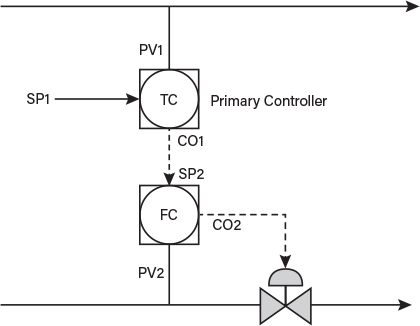
▲Figure 2. In a cascade control configuration, a primary controller’s output (CO1) provides the setpoint (SP2) to a secondary controller. The secondary controller provides a faster response to process disturbances. The controller output from the secondary controller (CO2) determines the valve position.
Feedforward control (Figure 3) can be accomplished by adding control action to a standard feedback controller. In the example in Figure 3, a temperature transmitter (TT) and temperature controller (TC) perform the feedback function. An uncontrolled measured disturbance variable (DV) signal goes to the feedforward controller (FFC), which makes a preventive control move. Because the disturbance itself cannot be controlled, the feedforward controller adjusts the signal to the control valve to try to reduce the impact of the disturbance. This is similar to the way a driver steps on the accelerator before starting up a hill.
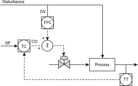
▲Figure 3. Feedforward control adjusts the signal to the control valve (from a standard feedback controller) to reduce the impact of a disturbance. In this case, a feedforward controller (FFC) makes a change to the controller output based on a measured disturbance variable (DV).
In ratio control (Figure 4), setpoints to several flow controllers (FCs) are coordinated to ensure that a consistent ratio of materials is fed into a process. The master flow signal may represent the total flow needed, and each component’s flow setpoint is adjusted so its flow controller (FC) can maintain the correct ratio of ingredients. Process variable measurements to the FCs are provided by flow transmitters (FTs).
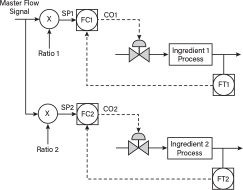
▲Figure 4. Under ratio control, setpoints to flow controllers FC1 and FC2 are coordinated to ensure that a consistent ratio of materials is fed into a process.
Model predictive control (MPC) uses mathematical models of the process dynamics and known process constraints to determine control actions. The MPC algorithm tries to maximize a controller objective by manipulating variables within the constraint envelope. The MPC then drives the setpoints of the lower-level regulatory controllers. Most MPC models are quite complex and require specialist engineers to develop, install, and manage the operation of them. Companies such as AVEVA, Honeywell, Aspen Technology, Cutler Technology, and Shell/Yokogawa provide MPC products and support.
Batch process control. Batch processes differ from continuous processes in many respects. Typically, batch processes are time-varying and nonlinear and often involve major load changes as the process proceeds. In some cases, this drives the need for adaptive controller tuning and/or split-range control. Laplace transforms and frequency domain control loop analysis techniques are rarely applicable or used.
Batch processes are used in plants that campaign the manufacturing of products (i.e., they use the same equipment for different products), so equipment setup, flow path adjustment, and scheduling are key challenges. Most processes are not totally manual or automatic but a coordinated mix of the two operations (which in itself is a challenge). Remote alarming may be needed, as operators are often in the field performing manual operations rather than in a control room.
Batch processes in the food, beverage, pharmaceutical, biotech, and similar industries require sanitary sensors and cleanable, sanitary valves (e.g., butterfly or ball valves). Such valves have different characteristics than more traditional control valves.
Control software should be organized to follow the ANSI/ISA-88 batch process control standard, which facilitates managing the process through its different sequential steps/phases and possible states (e.g., idle, pause, abort).
Discrete process control. Discrete process control typically involves operations on discrete units of process material or final product, often in the latter part of manufacturing operations when product is placed in individual containers, inspected, sealed, labeled, and packaged. Monitoring and control often consists of equipment and technologies different from those used in creating the bulk product, such as specialty sensors, vision systems (e.g., cameras), barcode printers and readers, radio-frequency identification (RFID) chips, and robotics.
National standards apply to some of these technologies, such as ANSI/RIA-R15.06, which provides guidelines for the manufacture and integration of industrial robots and robot systems, with an emphasis on safe use, risk assessment, and personnel safety. Current good manufacturing practices (cGMPs) may also apply, such as the U.S. Food and Drug Administration’s (FDA) requirements for proper identity labeling of pharmaceutical products.
As with other types of manufacturing control, engineers will often need to help design teams decide whether to use original equipment manufacturer (OEM) controllers or more standard general-purpose PLCs. OEM controllers may be a good fit for a specific application, but they are often proprietary, present a different HMI for engineers and operators to contend with, can be difficult to customize, and typically require third-party support. Using general-purpose PLCs may take time and resources for application development but otherwise overcome the limitations of OEM options.
Additional information on control strategies is available in the literature (6).
Software tools
The HMI encompasses both the hardware and the software used by the operator to manage the process. In older plants, the HMI was simply buttons, dials, lights, and paper chart recorders. In a modern facility, the HMI is typically displayed on computer consoles running specialized software.
ANSI/ISA-101 is a standard to help developers and users throughout the lifecycle of the HMI. It includes HMI design considerations, implementation requirements, and operation considerations.
Engineers should learn to verify the information displayed on the HMI screen before making rash decisions. For example, the displayed controller output is only the signal sent to the valve. The actual valve position could be quite different, due to physical constraints, configuration issues, or other factors.
Data historians are specialized databases designed to collect, store, and deliver process information. A large plant may produce well over 20,000 datapoints every second. Therefore, for certain analysis applications, data reduction algorithms are needed. For many batch processes, the data need to be tagged with the manufacturing lot number and perhaps even a batch process step identifier. Some data historians may include reporting or trending software to allow for optimized retrieval of large datasets. Commonly used historians include OSISoft PI, Aspen IP-21, AVEVA Historian (formerly Wonderware), and Canary Labs.
A chemical engineer supporting plant operations uses the historian daily to access process information. The engineer should understand that less-frequent sampling and data filtering and compression techniques are often used to reduce network loading and data storage requirements. When interpreting this data, engineers should be aware of the loss of precision in the data.
Control loop simulation software tools are commonly used in academia. In the industrial world, there are many types of complex process dynamics and many variations of the PID and other control algorithms. Simulation tools enable the engineer to experiment with control strategies and tuning options.
Specialty software packages. Sometimes, the functionality available in off-the-shelf control systems is not sufficient to accommodate all of a plant’s automation function requirements. In such cases, specialty software packages, often from third-party suppliers, may be available to help satisfy such requirements. Examples include MPC controllers, neural nets, fuzzy logic controllers, alarm loggers, alarm management databases, digital logbooks, advisory systems, trending/analysis tools, and real-time expert systems (a branch of artificial intelligence) (7, 8).
Care must be taken in integrating such specialty software packages with the rest of the control system. Compatibility, validation, and change control can be challenges.
Control performance
Control loop tuning is the process of selecting controller parameters for best performance. Best performance goes beyond basic stability criteria and may include criteria for speed of response, overshoot, rise time, and/or settling time. Most academic programs teach mathematical methods of loop tuning such as the Ziegler-Nichols tuning method. Several different methods are used in industry.
Sadly, in the industrial world, PID tuning is often treated like a dark art rather than a science. This may explain why as many as 30% of industrial controllers operate in manual mode. A contributing factor may be the large number of time-varying batch processes in industry, where the optimum tuning parameters near the beginning of the process are different from those at the end of the process.
However, software tools have made some significant progress in bringing the science of loop tuning to the plant. The academic approach (bump-model-tune) is certainly applicable and is still used with many modern software tools. Software tools also employ automated or semi-automated processes to perform loop tuning with much less intervention by the engineer. Loop tuning software vendors include Neles Expertune, Control Station, and ControlSoft.
Control loop performance management software monitors the performance of the controllers in the plant. The software evaluates instrumentation, controls, valves, and even the process. Diagnostics ensure that the control system is doing its job, thereby keeping the process operating optimally. Some DCSs have loop management tools; aside from the vendors of such DCSs, a few companies that specialize in control loop performance management include Neles Expertune, Control Station, and PAS.
Abnormal situation management
Chemical engineering students who conduct unit operations experiments typically perform most operations manually, including process start up and shut down, monitoring the process, and making any changes (e.g., to controller modes and setpoints) should the process encounter a problem. Automated response to abnormal situations, such as equipment malfunctions or failures, process upsets, or operator errors, are rarely discussed.
However, in industry, most operations are performed by configured software with a programmed recipe executed by the control system. Potential abnormal situations are anticipated in advance using standard tools and procedures such as hazard and operability analysis (HAZOP) and failure modes and effects analysis (FMEA). The goal of an FMEA is to minimize the consequences of component or system failures, reduce the frequency of their occurrence, and improve their detectability. The results of HAZOPs and FMEAs usually drive additional procedures and steps in process control recipes. In fact, it is not uncommon for most of a control recipe to be dedicated to abnormal situation management — a critical part of process control.
Industrial control involves considerable thought regarding abnormal situation management and can involve adding appropriate software interlocks, taking automated actions to override normal control, displaying possible root causes of an alarm on the operator console, and displaying pre-programmed advice for operators as to what actions to take.
In some cases, abnormal situation management may call for the process control recipe to automatically send the manufacturing process to a different state (e.g., hold, pause, or abort), depending on the abnormal situation. The ANSI/ISA-88 standard recommends such abnormal situation management practices for batch processes.
Alarm management
Part of abnormal situation management is the generation of alarms. Modern control systems support many different types of alarms (e.g., high, low, deviation, statistical). When they are misapplied or overused, alarms may be disruptive or generate confusion. Alarm management issues have contributed to major publicized disasters, such as the Chernobyl and Three Mile Island nuclear power plant incidents, the Deepwater Horizon and Exxon Valdez oil spills, the Bhopal chemical release, and the Texas City refinery fire. Alarm management best practices and requirements are numerous and are given in such standards as ANSI/ISA-18.2, “Management of Alarm Systems for the Process Industries” (9), and its international equivalent, IEC 62682.
Common alarm system problems include not having a defined plant alarm philosophy, configuring redundant alarms, using the alarm system for notifications in addition to abnormal situations, not setting alarm attributes to appropriate values, and not prioritizing alarms. All of these common problems contribute to the generation of nuisance alarms, which can cause information overload for operators during real plant upsets. Alarms may be intentionally or inadvertently disabled in many ways, which creates even more risks.
Proper alarm management requires a team of plant representatives who are knowledgeable of the manufacturing process to perform alarm rationalization. The team must agree on what option or numerical value to set for each of the attributes (i.e., properties) of each alarm to be configured into a system and document their decisions in a master alarm database. Attributes include setpoint, priority, class, type, deadband, time delay, and suppression status. Suppression can be important, for example, for batch processes in which the alarm is needed for some batch steps but not others. Some attributes may be a function of the batch process step, so they may have a different setpoint and/or priority for different batch steps.
Some desired alarm system functions may not be available as off-the-shelf functions in a vendor-supplied control system, so some customization or interface to third-party products (e.g., alarm loggers) may be needed. Attention to alarm management is needed near the beginning of a project and should be included in functional requirements; it should not be an afterthought when a control system is delivered.
Manufacturing execution systems
Most large plants have manufacturing execution systems (MESs) that support the management of manufacturing operations. These non-real-time systems are usually managed by the company’s information technology (IT) department. Such systems are responsible for scheduling plant operations and are sometimes the home of the master process control recipes (or portions of recipes such as ingredient lists) that control plant operations. They also often house the repository of batch records needed to document specific materials used in a manufacturing batch lot, document deviation investigations, and support release of the product so it can be sold.
Since MESs complement the use of process control systems (e.g., DCSs), MESs and plant process control computers are often connected in accordance with the ANSI/ISA-95 standard.
Documentation
The new engineer will need to learn to read, interpret, and modify many types of control system documentation. Although most graduates are familiar with process flow diagrams (PFDs) and piping and instrumentation diagrams (P&IDs), industrial control documentation may also include:
- functional requirements and system specifications
- contracts with engineering, procurement, and construction management (EPCM) firms
- control narratives
- validation and alarm philosophies
- master alarm databases
- procedures (e.g., change control)
- manufacturing tickets
- instrument specifications
- piping diagrams
- electrical wiring drawings
- logic diagrams
- control loop diagrams
- network diagrams
- factory acceptance tests and site acceptance tests.
Many of these are not simply as-designed engineering documents, but are working documents that require updates to reflect the current as-built status of the plant.
Closing thoughts
While the academic environment provides chemical engineers with a solid understanding of linear control theory, there remains a significant gap between this aspect of process control and the much broader range of industrial process control equipment, software, requirements, best practices, technologies, and challenges that a new graduate will encounter when starting their first job in industry. The knowledge gap includes many of the topics mentioned in this article, including the several national standards and regulatory requirements that must be considered when developing and supporting industrial process control systems.
New graduates who receive an assignment in process engineering should strive to find applicable resources (e.g., Ref. 10) and mentors in the plant environment and gain exposure and training on existing plant control systems and procedures, as well as all applicable regulatory requirements and best practices. The new graduate might also consider attending some of the many excellent process control courses offered by technical societies such as AIChE and International Society of Automation (ISA).
Literature Cited
- Alford, J., and T. Edgar, “Preparing Chemical Engineering Students for Industry,” Chemical Engineering Progress, 113 (11), pp. 25–28 (Nov. 2017).
- Buckbee, G., and J. Alford, “Automation Applications in Bio-Pharmaceuticals,” ISA, Research Triangle Park, NC (2008).
- Sands, N., and I. Verhappen (Eds.), “A Guide to the Automation Body of Knowledge,” ISA, Research Triangle Park, NC (2018).
- Whitt, M., “Successful Instrumentation and Control Systems Design,” ISA, Research Triangle Park, NC (2012).
- Buckbee, G. C., “Process Control Basics,” ISA, Research Triangle Park, NC, ISBN: 978-1-64331-130-2 (expected early 2021).
- McMillan, G. K., and P. H. Vegas, “Process/Industrial Instruments and Controls Handbook,” 6th Ed., McGraw-Hill Education, New York, NY (2019).
- Alford, J., et al., “Real Rewards from Artificial Intelligence,” Intech, 46 (4), p. 52 (Apr. 1999).
- Alford, J., et al., “Online Expert-System Applications; Use in Fermentation Plants,” Intech, 46 (7), p. 50 (July 1999).
- ANSI/ISA-18.2 “Management of Alarm Systems for the Process Industries,” ISA, Research Triangle Park, NC (2016).
- Riggs, J. B., et al., “Chemical and Bio-Process Control,” 5th Ed., Ferret Publishing, Austin, TX (2020).
Disclaimer
This article includes the names of process equipment and software vendors for educational purposes only. No endorsement of those vendors and/or products is intended.

Copyright Permissions
Would you like to reuse content from CEP Magazine? It’s easy to request permission to reuse content. Simply click here to connect instantly to licensing services, where you can choose from a list of options regarding how you would like to reuse the desired content and complete the transaction.