
A chemical engineer’s knowledge of the process is an asset to batch process automation efforts. Learn what aspects of batch process automation deserve special consideration, as well as issues on the horizon for this developing field.
Batch process automation is far more challenging than automating a continuous process. The controls handle numerous transitions, such as those between loops that operate intermittently, which must be made as smoothly as possible. Product safety is another concern because of the potential to charge the wrong chemical or charge material at the wrong time. Batch processes are substantially more labor-intensive than continuous processes. And, programming tools familiar to both process engineers and chemists are needed to help ease the automation effort.
This two-part article examines batch automation. Part 1, which appeared in the August issue, described the different types of batch processes and explained the history and current status of batch automation (1). Here, Part 2 focuses on the issues that deserve special consideration related to the often-difficult task of automating a batch process.
Control deficiencies
Control deficiencies take a variety of forms, ranging from the extremely simple to the very complex. A basic example can be constructed from the flow loop in Figure 1. The piping contains two valves — a control valve and a block valve — as well as a flow transmitter (FT) that provides the process variables (PV) to the flow controller (FC) whose output is the control valve opening.
The batch controls terminate material transfers by closing the block valve. However, if the flow controller remains on auto with the setpoint used during the material transfer, the output of the flow controller is driven to its upper output limit, which usually means that the control valve is fully open. When the block valve is opened for the next transfer, the flow initially surges. Flow controllers recover rapidly, but the process is subjected to a bump.
Output tracking — which forces the output of the controller to a specified value under certain conditions — can prevent such bumps. Output tracking for the flow controller can be configured so that:
- it is active when the block valve is closed, and
- the value of the controller output is 0% (or the lower output limit of the flow controller).
This is easy to do, but it is like dotting i’s and crossing t’s — and there are so many that some will inevitably be missed.

▲Figure 1. The controls terminate material transfers by closing the block valve. If the controller is left on auto with the setpoint used during the material transfer, the control valve will be driven fully open. The next material transfer will begin with a flow surge and cause the process to experience a bump.
Batch process controls work, but typically with a few flaws. Unless personnel understand both the process and the controls, flaws tend to remain. Rarely do these issues prevent the plant from making salable product, so flaws are, for the most part, nuisances — primarily to process operators.
More difficult issues arise when the control deficiencies stem from some aspect of the plant equipment. Reactors in batch facilities are commonly equipped with heating-and-cooling jackets. These jackets can be switched between heating and cooling per the product recipe or based on process conditions. The following example pertains to those that must be switched based on process conditions, usually while reactions are occurring within the reacting medium.
The split-range technique is a well-known control method for switching a jacketed vessel, such as the one in Figure 2, between cooling and heating (2). To transition from cooling to heating, the cooling-water valve closes then the steam valve opens; to transition from heating to cooling, the steam valve closes then the cooling-water valve opens. For this to perform properly, the equipment must be able to sustain cooling and heating rates close to zero.
The configuration in Figure 2 cannot sustain a heating rate close to zero. When steam is applied, the condensate within the exchanger is forced to the condensate return. The minimum steam pressure within the exchanger is atmospheric pressure or slightly above, and the steam temperature is 100°C or a little higher. The driving force for heat transfer is the difference between the condensing steam temperature and the temperature of the water in the recirculation loop. Unless the temperature in the reacting vessel is above 100°C, the minimum temperature difference will be greater than zero, which translates to a minimum heat-transfer rate greater than zero.
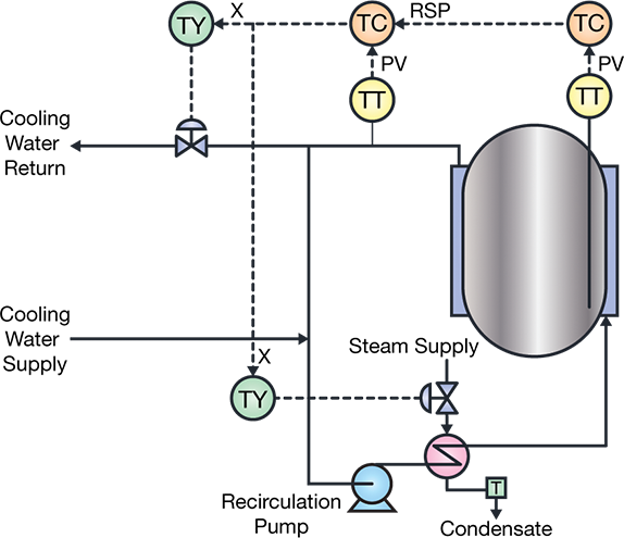
▲Figure 2. Temperature transmitters (TT), controllers (TC), and characterization functions (TY) open and close the control valves on the cooling water and steam lines to regulate the temperature of the jacketed vessel.
The split-range controller will not be able to effect a smooth switch between heating and cooling. The switch to steam will result in a higher heat-transfer rate than desired, requiring a quick switch back to cooling. This cycle will continue until the required heat-transfer rate is greater than the minimum heat-transfer rate that can be sustained.
Although this irregular operation is often blamed on the process controls, the problem actually lies within the process. Equipment modifications need to be made, such as moving the control valve for heating from the steam supply to the condensate return.
A basic understanding of both the process and the controls is necessary to effectively analyze this problem, and control issues typically remain if the technical know-how is not available.
Throughput in a batch facility
To tune a proportional-integral-derivative (PID) controller, the tuning coefficients must be aligned with the process characteristics. Anything that significantly affects the characteristics of the process degrades the performance of the controller. Throughput is one parameter that almost always affects the process characteristics. For a continuous process, throughput is equivalent to production rate. Most continuous processes operate at essentially constant production rates, with the exception of utility processes such as boilers, water treatment, etc.
How is throughput defined in a batch plant? The average throughput is the amount of product produced by a batch divided by the batch time. For reacting vessels, the instantaneous throughput is the rate of the reaction that produces the desired product. For exothermic reactions that occur in a vessel maintained at a constant temperature, the throughput depends on the rate at which heat is removed from the...
Would you like to access the complete CEP Article?
No problem. You just have to complete the following steps.
You have completed 0 of 2 steps.
-
Log in
You must be logged in to view this content. Log in now.
-
AIChE Membership
You must be an AIChE member to view this article. Join now.
Copyright Permissions
Would you like to reuse content from CEP Magazine? It’s easy to request permission to reuse content. Simply click here to connect instantly to licensing services, where you can choose from a list of options regarding how you would like to reuse the desired content and complete the transaction.