
Use scenario-based fire modeling to determine the most effective combination of active fire protection and passive fire protection for your facility.
When designing an effective fire protection system, engineers need to implement both active and passive fire protection measures. Active fire protection (AFP) is required to manage and mitigate process fires; passive fire protection (PFP) prevents escalation.
This article describes how to determine the optimum balance of AFP and PFP through quantitative risk-based fire modeling techniques. It reviews current fire protection standards — both prescriptive and scenario-based — and addresses the challenges of scenario selection. It also covers additional factors that should be considered when designing a fire protection system, including detection, drainage, isolation and blowdown systems, and the timing of emergency response activities.
Prescriptive vs. performance-based design
Numerous fire protection guidance documents and regulations provide advice for developing an effective fire protection plan. These guidelines promote both prescriptive and performance-based approaches to fire safety. Table 1 compares some of the key sources of guidance (1–6).
| Table 1. Industry standards, best practices, and other publications provide fire protection guidance. | ||
| Publication | Description | Ref. |
| API Publication 2218 Fireproofing Practices in Petroleum and Petrochemical Processing Plants |
| 1 |
| API Recommended Practice 2001 Fire Protection in Refineries |
| 2 |
| NFPA 30 Standard Flammable and Combustible Liquids Code, 2012 |
| 3 |
| UL 1709 Standard Standard for Rapid Rise Fire Tests of Protection Materials for Structural Steel |
| 4 |
| FABIG Technical Note 11 Fire Loading and Structural Response |
| 5 |
| CCPS Guidelines for Fire Protection in Chemical, Petrochemical, and Hydrocarbon Processing Facilities |
| 6 |
Prescriptive fire safety design follows specific industry codes and government regulations that spell out the requirements for an effective fire safety system. Prescriptive design codes have the benefit of providing clear and direct measures to be taken in the design of the facility.
Performance-based fire safety codes specify a safety goal to be met through the design of the facility’s fire safety measures. Performance-based codes (i.e., risk-based design) provide flexibility in the design of a fire-safe facility, because any means suitable may be employed to meet the goal.
Prescriptive codes provide a strong basis for fire safety design. They are intended to be all-inclusive codes for typical designs based on the intended function of the facility. For innovative or unique facility designs, the flexibility afforded by performance-based codes allows designers to implement novel approaches to achieve their fire safety goals.
Neither method of fire safety design necessarily replaces the other; they are not in competition. Rather, performance-based design codes can supplement prescriptive codes. When the two approaches are used in conjunction, a fire safety design plan is not limited and the fire protection systems are effectively designed with the facility’s unique layout in mind.
Active vs. passive options
Active fire protection systems require automatic or manual intervention for actuation, while passive fire protection systems do not require any form of actuation.
Active fire protection. AFP systems involve the application of fire extinguishing or other protective media to surfaces that are on fire or exposed to heat during an emergency. Common media include foam, powders, gases, and coolants (e.g., water mists, sprays, or deluges) (7).
AFP may be used to:
- cool fire-exposed equipment and structures
- reduce the temperature rise in exposed equipment
- apply foam to extinguish hydrocarbon pool fires.
AFP is intended to extinguish a fire, protect equipment in the vicinity from the damaging effects of fire, and reduce the risk of escalation of the incident. However, AFP systems cause the smoke layer to destratify, which reduces visibility and increases the risk of smoke inhalation (Table 2).
| Table 2. Active fire protection holds several advantages over passive protection, but also has some disadvantages. | |
| Advantages | Disadvantages |
| Avoids fire spreading | Smoke layer destratifies |
| Improves accessibility of the fire site | Requires more-complex equipment |
| Better protects infra-structure | Reduces visibility |
Passive fire protection. The primary function of PFP is to contain fires or slow their spread in order to limit damage to the facility and give occupants more time to escape, evacuate, or muster in a safe area (Table 3). PFP does not require energized initiation or any motion to activate it, and it is an effective barrier to prevent escalation (1).
| Table 3. Passive fire protection offers several advantages over active fire protection, but it also has limitations. | |
| Advantages | Disadvantages |
| Avoids structural disintegration | Does not prevent fire spreading |
| Slows the spread of fires | Does not provide cooling |
| Does not require activation, limiting potential personnel exposure | Increases corrosion of materials covered by PFP |
| Reduces escalation potential | Reduces accessibility of equipment for inspection and maintenance |
| Requires more space | |
| Requires maintenance | |
PFP includes materials that are designed to limit temperatures and prevent excessive heat absorption within process plant equipment, structures, and vessels (7), such as:
- fire-rated walls, doors, and support structures
- insulation
- drainage sumps
- secondary-containment structures (bunds)
- compartmentalization.
The main challenge associated with PFP is determining how much additional fire resistance is required beyond the AFP, and developing an effective PFP preventive maintenance plan. Generally speaking, the primary focus should be to design a system that has the capability to contain and control a fire, which usually is the function of AFP. However, PFP is effective in preventing critical escalation of the fire, especially when it works in conjunction with AFP. Additionally, PFP minimizes the need for personnel in the fire area.
Fire hazard analysis
The first step in fire protection system design is to conduct a fire hazard analysis (FHA) to quantify and help you understand the fire hazard, which is essential for risk-reduction decision-making. An FHA can be a stand-alone hazard evaluation or integrated into an overall risk assessment, and it can be performed on a proposed design or an existing facility.
An FHA typically documents the inventory of a potential flammable or combustible release, identifies the credible fire scenarios, estimates the possible outcome of a fire, and determines the potential impact on personnel, assets, and the environment.
The products of an FHA include (6):
- an inventory of fire hazards, including quantities
- a comprehensive picture of the fire hazard, including potential magnitude and duration
- an estimate of the potential impact of a fire on personnel, equipment, the community, and the environment
- a list of appropriate mitigation options.
An FHA should consider several potential fire hazards, specifically jet fires and pool fires. Each type of fire has unique characteristics and implications for mitigation.
Jet fires
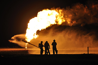
▲ Figure 1. A jet fire results from combustion of a fuel that is continuously released in a particular direction.
A jet fire (Figure 1) is a turbulent diffusion flame resulting from the combustion of a fuel continuously released with some significant momentum in a particular direction or directions (8). Three jet situations must be considered: gaseous jet, flashing liquid (two-phase) jet, and stable liquid jet. The high heat fluxes from a jet fire on impacted equipment or infrastructure can cause significant structural damage due to direct impingement. Hence, jet fires are often considered a key risk associated with onshore and offshore accidents.
Current industry practice focuses on analyzing the flame length of potential jet fires, as well as the thermal radiation intensity with respect to distances between fire sources and plant equipment, buildings, populations, etc. The extent of impingement into an affected area is considered, as well as the need for PFP, emergency depressurization, and other mitigation options (8).
The characteristics of a jet fire depend on the composition of the released material, release conditions, release rate, release geometry, and ambient wind conditions. To assess the impact from a jet fire to the surrounding targets, the jet fire scenario needs to be identified by first calculating the fuel discharge rate. The fuel discharge rate depends on the pressure and temperature in the vessel, the quantity of material that could be released and the material’s properties, and the shape of the opening through which the release would pass. Next, the physical size of the resulting fire (flame size) is quantified, and then the heat release rate, which is mainly governed by the mass flowrate and the properties of the fuel being released, is calculated. After that, heat-transfer modeling determines the heat transfer from the jet flame to the adjacent targets and their radiative exposure. These steps are the most straightforward approach to assessing jet fire impacts.
Additionally, the high-pressure release of a jet fire can impart kinetic energy onto objects and personnel. Effective means of jet fire mitigation include walls designed to withstand direct impingement of jet fires (J rated), deluge systems, and blowdown systems.
Pool fires
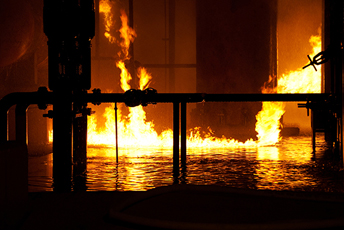
▲ Figure 2. A pool fire burns above a horizontal pool of vaporizing flammable fuel.
A pool fire (Figure 2) is a turbulent diffusion fire burning above a horizontal pool of vaporizing flammable fuel where the fuel has zero or little initial momentum (8). A pool fire typically begins with the release of a flammable liquid stored at a temperature below its normal boiling point — or under pressure above its normal boiling point — from process equipment into an open area or within containment. If the flammable liquid is stored under pressure, then a fraction of the liquid will flash into vapor, and the unflashed liquid will remain and form a pool in the vicinity of the release.
Pool fires are analyzed by determining the pool size and the release duration, which are then used to calculate the flame height, the duration of the burning pool, the flame temperature, and thermal radiation to external targets (6).
The primary concern regarding pool fires is prolonged exposure to thermal radiation. Effective barriers for mitigation of pool fire exposure include fire walls rated for hydrocarbon radiation exposure (H rated), deluge systems, drainage systems, and insulating coatings.
Flash fires
A flash fire is the advancing flame front of an ignited vapor cloud. The cloud may be ignited at any point between the chemical’s upper flammability limit (UFL) and lower flammability limit (LFL). Although it presents significant personnel hazards (any outdoor personnel caught within the flash fire envelope are considered immediate fatalities), flash fire itself does not cause significant structural damage, unless the flash fire burns back to a sustainable release source and triggers a jet fire.
Unconfined flash fires do not generally create significant overpressures, and as such their damage is limited to thermal impacts only. Proper shielding and blowdown systems limit the severity of flash fires.
Selecting fire scenarios
A key element of FHAs is the selection of scenarios to represent the potential fire hazards. In theory, the number of possible leak sizes is infinite, ranging from a pinhole to a full rupture of piping or equipment. It is impractical to investigate all possibilities. Thus, it is important to select representative leak sizes that will allow a reasonable range of fire scenarios to be evaluated. Engineers performing FHAs typically define generic sizes for small, medium, and large releases as the basis for fire modeling and determining the potential impact at various release locations. The Center for Chemical Process Safety (CCPS) provides guidance on selecting generic release hole sizes for typical FHAs (Table 4) (6).
| Table 4. These typical hole sizes will allow for evaluation of different fire scenarios during modeling and analysis (6). | ||
| Release Category | Release Size Range | |
| Small | 0.1–0.4 in. | 3–10 mm |
| Medium | 0.4–2 in. | 10–50 mm |
| Large | 2–6 in. | 50–150 mm |
| Rupture | Full-bore (equipment diameter) | |
Modeling a range of release sizes reduces the chances that the study will overlook hazards. Different release sizes have different implications with relation to impact potential. Small and medium releases have longer durations and a greater potential for escalation and domino effects. Large and rupture releases may have large hazard zones, but short durations that may not cause structural failure.
In addition, maximum credible cases need to be defined for other types of incidents, such as catastrophic ruptures of pressurized storage vessels, spills from transport vessels, boiling-liquid expanding-vapor explosions (BLEVEs), etc. The term maximum credible refers to events that are technically feasible but may still be highly unlikely.
Worst case vs. credible
CCPS defines a worst-case scenario (WCS) as a release involving a hazardous material that would result in the most severe consequences. The worst-case approach can be used as a decision-making support tool because it is con-servative and always predicts the worst outcomes. These worst-case scenarios typically consider a near-instantaneous depletion of the maximum amount of hazardous material stored at a facility that could be released upon the rupture of a line or storage vessel, assuming the failure of mitigation and safety systems.
A disadvantage of the worst-case approach is that ignoring safeguarding features tends to move discussion away from improving such safety measures (9). When using the worst-case approach, the probability of an accident is generally ignored.
CCPS defines a maximum credible event as the most severe incident, considering only the consequences of incidents that are deemed plausible or reasonably believable. For example, certain accidents that occur frequently may not be of concern because the quantities of chemicals released are small and/or they are managed effectively by proper control measures.
Effective and sufficient safeguards can reduce the likelihood of an event or reduce the potential outcome of an event. Consider both plausibility and the level of the threat when determining the number and effectiveness of safeguards in the assessment process.
Modeling scenarios
The use of computer-generated fire models has grown substantially in recent decades and is widely accepted by designers and regulators. These models use mathematical methods to estimate fire impacts to structures and equipment. The complexity of fire models ranges from relatively simple formulas that can be solved analytically, to hybrid sets of differential and algebraic equations that must be solved numerically on a computer (6).
In the conceptual or proposed design stage, simple models such as spreadsheets with formulas or public domain calculation tools can be used. To obtain more comprehensive analyses for impact estimation within a limited time frame, commercial software that predicts free-field hazardous outcomes (e.g., DNV’s Phast) may be utilized. Nevertheless, simple modeling tools may predict an overly conservative jet fire, for example, without considering the obstacles in the path of the flame and the ventilation conditions.
A more complex consequence analysis may be performed using computational fluid dynamics (CFD) tools dedicated to fire simulation. For example, Kameleon FireEx (KFX; commercialized by ComputIT) includes combined models for all the effects that are critical during a fire’s development (e.g., source, combustion, radiation, soot, air, smoke, and wind). KFX applies a 3D model of the facility, so it accounts for geometries and obstructions that will affect or limit radiation on surrounding structures.
Impact analysis
In an FHA, impact analysis involves evaluating the identified credible fire scenarios to determine the potential impact the fire could have on equipment and structures. An impact analysis should consider:
- radiation and time exposure. The potential thermal radiation and its duration determine the heat flux emitted by the fire and the exposure of the surrounding equipment and structures. The type of fire (i.e., jet or pool) is also an important consideration, as the different types have different exposure mechanisms.
- failure of equipment and structures. Equipment and structure failures are evaluated by comparing failure criteria against heat flux and time of exposure. Failure criteria depend on several factors, such as material type and properties, dimensions, heat type and flux, nature of exposure (e.g., flame impingement or engulfment), etc.
- protection by PFP and deluge systems. If protective systems are in place, they must be acknowledged in the impact analysis, because they reduce the impact of fire on equipment and structures.
- domino and escalation events. An impact analysis should consider the potential for containment failure that would allow the fire to spread to adjacent areas of the facility. This escalation and exacerbation of the event could cause the collapse of tall vessels, towers, pipe racks, vent system supports, and other equipment, as well as a BLEVE that produces overpressures and launches projectiles.
Defining the AFP/PFP balance
To identify the appropriate fire resistance for the facility, designers should determine what fire hazards will be major credible scenarios at the facility. Fire resistance rating is influenced by AFP resources. For example, deluge systems increase the fire resistance time of PFP significantly.
After conducting an FHA, choose which areas require AFP and PFP based on potential release locations, fire envelopes, and fire characteristics determined in the FHA. Consider:
- equipment and personnel that could be exposed
- operating conditions in exposed areas (i.e., process temperature, pressure, and hazardous materials in and around the release)
- equipment spacing, layout, and the potential for escalation due to adjacent fire exposure
- estimated duration of fire
- type of fire (i.e., pool fire, jet fire, vapor cloud explosion, liquid spray, etc.).
Prescriptive guidelines specify how much and where PFP and AFP systems should be installed. The main challenge is determining how much fire resistance is required.
The main objective of the fire safety design should be to enable personnel to reach a safe location. Therefore, the primary functions of fire safety systems are to protect escape routes, mitigate the severity of the event, and prevent escalation. Secondary goals may be to limit damage to assets.
For each of the facility areas that may be impacted by major fire scenarios, planned or existing levels of PFP and AFP within that area of the facility must be documented. If the facility is in an early design phase, the planned PFP and AFP will most likely be based primarily on prescriptive standards.
Use a workshop approach to assess the needed balance of AFP, PFP, and other safety systems. First, assemble a team of experts who are knowledgeable about the process units, the facility’s fire protection systems, and/or the site’s fire response methodology. At the workshop:
1. Consider a range of fire scenarios that may be possible for the unit. Ensure that the selected scenarios are representative of the possible fire hazards and reflect several different locations within the unit. Depending on the size of the unit, the number of scenarios could be as many as five.
2. Evaluate each scenario and the possible fire progression. Discuss the scenario from the moment of release to extinguishment. Identify all present barriers that are available to mitigate the fire scenario.
3. Decide on minimumAFP and PFP requirements. Based on the discussion of the different passive and active barriers required to mitigate the different release scenarios, reach a consensus on the minimum AFP and PFP requirements for the unit. Different PFP ratings might be recommended for different sections of the unit and different structures or equipment. Since AFP and PFP complement each other, the AFP needs must be reviewed to make sure it can supply the necessary coverage and fire-water; if the AFP is found to be lacking or insufficient, the PFP can be adjusted accordingly.
Safety barriers to consider
The effectiveness of some safety barriers varies depending on the characteristics of a fire. For example, drainage will do little to limit the amount of inventory released if the release is a high-pressure vapor that causes a jet fire. Or, it might not be possible to quickly isolate a large volume of liquid released from a tank.
The functions and characteristics of each type of safety barrier must be considered in the assessment.
Gas and fire detection. Detectors warn of loss of containment and developing hazards. Remote detection of releases is important to facilitate quick activation of emergency alarms, isolation and depressurization systems, and active fire-water deluge systems. Detectors can be classified based on the hazards they detect.
Fire detectors generally fall within one of three categories (6):
- heat detectors that sense the heat of a fire
- smoke detectors that sense the combustion products of a fire
- flame detectors that identify a flame by sensing the infrared (IR) or ultraviolet (UV) light it emits.
Gas detectors detect gas clouds of sufficient size that, if ignited, could produce a flash fire or explosion overpressure (6). The quicker a release is identified, the faster operators can react to limit the potential spread and evolution of the scenario.
Monitoring and closed-circuit television (CCTV). Facility monitoring is an important piece of the collective fire protection barrier, because it can alert operators and allow them to monitor remotely any process upset, loss of containment, or fire. Fire and gas detectors are an integral part of this system, as they can provide feedback to monitoring stations such as the control room.
CCTV can be used to analyze digital images and identify the characteristics of developing hazards and fires. It has the advantage of being able to remotely assess the effectiveness of fire protection systems and assist with staging the response, thereby mitigating the risk associated with in-person fire investigation.
Isolation and depressurization. An emergency shutdown (ESD) system can isolate and depressurize process equipment. An ESD system ensures facilities are shut down in a safe and controlled manner. ESD systems can be fully integrated and linked to emergency shutdown valves (ESDVs), which on activation isolate sections of the unit by restricting the flow of hydrocarbons or other flammable materials and allowing blowdown (controlled depressurization).
Blowdown systems vent and depressurize facilities. The design of blowdown systems (i.e., simultaneous or staggered, manual or automatic actuation) should be included in the fire protection requirement assessment.
Operational gas detection and automated shutdown and isolation systems are effective mitigation measures for all fire scenarios because they reduce the available inventory of flammable material.
Layout. Discussing the plant layout in relation to potential fire events, with a focus on the equipment and personnel that would be most impacted, will enable you to narrow down the facility’s fire safety needs. Layout considerations for effective fire safety design include:
- proper fire-water coverage of equipment
- constraints on the fire response team’s access
- constraints on the escape route and access to it
- adequate detection coverage.
When reviewing layout issues that impact the balance of AFP and PFP requirements, consider these questions:
- Are jet or pool hazards specific to certain parts of the unit?
- Are any sections of the unit congested so that it would be difficult to apply fire-water?
- Will fire response teams have difficulty accessing any areas of the facility?
Deluge systems and fire-water monitors. Deluge systems can spray water or a foam-water mixture. Upon flame or gas detection, the deluge system is triggered to immediately attempt to mitigate the fire. Water deluge systems are used to prevent escalation by cooling equipment and structures adjacent to a fire that could experience thermal radiation exposure. Foam-water deluge systems are used to extinguish fires. Prescriptive requirements specify the installation of automatic deluge systems around equipment and pumps operating under certain conditions.
Fire-water monitors that apply fire-water, either to a fixed location or to a location chosen by an operator or the fire response team, should be installed around the unit. The location and fire rating of these monitors should be reviewed to ensure they are in optimal locations and provide the needed fire-water flowrate.
Bunds. A secondary-containment dike, or bund, limits the size of a liquid pool when a release occurs within the bunded area. Bunds should be built around major equipment if a release from that equipment could impact adjacent equipment, escape routes, or personnel. The height of a bund should be based on a worst-case (e.g., total) inventory release; if the bund is incorrectly sized, the release could spill over the bund walls. Tank bunds should be designed to contain 110% of the tank’s maximum operational capacity (7).
The protection afforded by the bund may reduce the level of PFP and AFP needed elsewhere, as long as the bund arrangement does not cause thermal radiation from the pool fire to impact other targets. The levels of thermal radiation from a pool fire mitigated by the bund should be verified by an FHA. If the facility credits the bund as a vital mitigation barrier for a pool fire, the bunds must be maintained to specification.
Drainage. Drainage is an important means for controlling pool fires. The placement of drainage basins and cement gradient lines for all potential pool fire scenarios identified during the FHA should be examined closely. The drainage capacity, placement of drains, and gradient directions should all be considered when determining whether the size of a pool fire can be limited or reduced. Potential equipment impingement by a pool fire flowing toward the drains should also be evaluated, and additional fire protection should be considered for equipment near the drain that is likely to be impinged.
The protection provided by the drainage system may also reduce the level of PFP and AFP required elsewhere, if the drainage system design does not cause radiation from the pool fire to impact other significant targets. The radiation mitigated by the drainage system should be verified by an FHA. To consider the drainage system a key mitigation barrier, it must be maintained to specification through testing and regularly scheduled preventive maintenance.
When designing a drainage system, consider:
- Surface drainage capability must be adequate, as this is a means for preventing the spread of flammable liquids from one operating area to another (9).
- Adequate collection, drainage, and oil/water separation facilities should be provided for runoff from the unit. These should include treating systems to prevent carryover of petroleum, production byproducts, and other pollutants into the sea, rivers, or other environmentally sensitive areas (6).
- The drainage system must be able to cope with increased flow during fire-fighting, as the fire-water could exceed the normal drainage capacity and cause flooding.
Fire squad emergency response time. Active and passive fire protection should be considered as complementing each other to provide sufficient time for emergency responders to assess the fire and then intervene and/or blow down the unit. The fire squad is critical for controlling fire events. The sooner the fire squad is able to respond, the faster a fire event can be evaluated and properly mitigated.
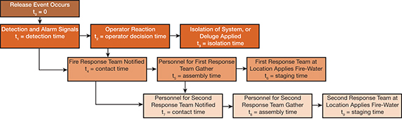
▲ Figure 3. The fire squad response time is measured from the time of the release to the time the response team begins active fire-fighting. The sooner the fire squad is able to respond, the faster a fire event can be assessed and mitigated.
The estimated fire squad response time is measured from the point of release or ignition until the fire squad initiates active fire-fighting (Figure 3). To avoid underestimating the fire squad response time, consider the worst-case scenario conditions — the night shift, personnel are offsite and need to travel to the site to stage the response, etc. Evaluate the fire squad response timeline with experienced fire squad members to ensure its accuracy.
Based on the estimated fire squad response time, define the minimum required performance time of the PFP for key equipment to avoid escalation, identify mustering locations for safe refuge, and determine primary escape routes to allow successful evacuation.
The chief goal of fire safety design should be to ensure safe escape and prevention of escalation until the fire squad is able to effectively respond. However, response time can vary, so potential response time deviations need to be understood. Because it is prudent to err on the side of safety, a PFP performance time of double the fire squad response time is recommended.
Additional challenges
During the assessment of fire protection systems, certain challenges need to be considered.
OSBL pipe racks. Outside battery limit (OSBL) pipe racks connect different units within a facility. These pipe racks may carry a variety of flammable materials and may come within close proximity to multiple units, which can expose the piping to many different hazardous conditions.
The challenge is assessing what fire protection to apply to the pipe racks and where. If the pipe racks are not properly protected from potential fire hazards, direct impingement can cause pipe rack failure. If the contents of the pipes vary significantly, a release from the pipe racks could create both pool fires and jet fires. Therefore, the contents of the pipe rack in different areas of the facility need to be considered when determining potential escalation scenarios.
Extreme worst-case scenarios. Using the release scenario that will cause the most severe consequence can yield results that are too severe to provide any meaningful insight into where to focus protection efforts — for example, if the entire unit is within the hazard zone. From a safety perspective, applying the most thorough protection on all equipment and structures is an extremely effective fire safety regime, but from an economic perspective, that may not be feasible.
Hence, it is important to qualify the severity of fire scenarios identified in the FHA based on more than area of effect alone. The likelihood of the fire scenario to occur should be part of the discussion about what fire events to safeguard the facility against. Considering only plausible worst-case scenarios allows you to optimize the fire protection system in terms of both safety and cost.
Spherical tanks. The application of insulation to certain structures can prove challenging, and needs to be considered in the design of fire protection systems. Due to their high surface-area-to-volume ratio, spherical storage tanks have a great deal of area that requires protection. Deluge systems on a spherical tank require more water than a cylindrical tank of the same volume for equivalent water coverage. A fire-water demand study should be conducted to verify that the facility can meet the demands of the installed AFP systems.
In closing
Striking the right balance between passive and active fire protection measures is critical to designing and maintaining a safe facility. Conducting an FHA, evaluating the worst-case scenarios, and using modeling tools and impact analysis to choose a mix of AFP and PFP systems will put you on the right path toward achieving this balance. Each unit and facility is unique and has its own special considerations. A workshop approach to evaluating the relevant barriers is an effective way to address a facility’s fire protection needs.
Literature Cited
- American Petroleum Institute, “Fireproofing Practices in Petroleum and Petrochemical Processing Plants,” Publication No. 2218, 2nd ed., API, Washington, DC (Dec. 2010).
- American Petroleum Institute, “Fire Protection in Refineries,” Recommended Practice 2001, 9th ed., API, Washington, DC (April 2012).
- National Fire Protection Association, “Flammable and Combustible Liquids Code,” NFPA 30, NFPA, Quincy, MA (2012).
- Underwriters Laboratories, “Standard for Rapid Rise Fire Tests of Protection Materials for Structural Steel,” UL 1709, Northbrook, IL (1991).
- Fire and Blast Information Group, “Fire Loading and Structural Response,” Technical Note 11, FABIG, The Steel Construction Institute (Mar. 2010).
- Center for Chemical Process Safety, “Guidelines for Fire Protection in Chemical, Petrochemical, and Hydrocarbon Processing Facilities,” CCPS, New York, NY (2003).
- Energy Institute, “Part 19; Fire Precautions at Petroleum Refineries and Bulk Storage Installations,” 2nd ed., EI, London, U.K. (Jan. 2007).
- Health and Safety Executive, “Fire and Explosion Strategy — Issue 1,” Hazardardous Installations Directorate, Offshore Div., HSE’s Energy Div., Liverpool, U.K. (Feb. 2003).
- Pitblado, R., et al., “LNG Decision Making Approaches Compared,” Journal of Hazardous Materials,130 (1–2), pp. 148–154 (2006).
1

Copyright Permissions
Would you like to reuse content from CEP Magazine? It’s easy to request permission to reuse content. Simply click here to connect instantly to licensing services, where you can choose from a list of options regarding how you would like to reuse the desired content and complete the transaction.