
Many factors affect the flowrate of bulk solids. This article reviews the underlying physics of solids flow and explains how to calculate the discharge rate of solids from processing and handling equipment.
The need to estimate the discharge rate of granular material leaving a hopper dates back to ancient times and the invention of the hourglass filled with fine sand. In the modern chemical process industries (CPI), accurate prediction of discharge rates of particulate solids from process equipment or storage vessels (e.g., silos, bins, hoppers) is essential for any solids handling or processing operation. The bulk solids should discharge from the vessel outlet reliably and smoothly, and at a mass flowrate that satisfies the requirements of the downstream process. Equipment should be designed so that the unrestricted discharge rate out of a storage vessel always exceeds the processing capability of the downstream unit operation.
Uncontrolled discharge (commonly called flooding or flushing), either extremely high or erratic, is problematic. To control or throttle the feed rate to the downstream process, a feeder or discharge valve is typically installed at the outlet of the bin or hopper. However, some feeders, such as screw feeders and belt feeders, are not able to stop the uncontrolled discharge of powders out of bins caused by flooding. This can cause a processing upset or even spillage. Flooding of powders can be prevented if the fundamental causes, such as insufficient deaeration or aeration at the outlet due to a negative pressure gradient, are properly addressed.
As our understanding of bulk solids behavior has evolved, so has our ability to appreciate the myriad factors influencing the discharge rate. Coarse particulates (average particle size dp ≥ 500 μm) must be treated differently than fine powders. The design and sizing of many common types of equipment, such as silos and bins, filling machines, slot flowmeters, slidegate valves, silo blenders, and fertilizer spreaders, depend on our ability to predict discharge rates.
Differences between fluids and bulk solids
The physics of bulk solids is markedly different than the physics of liquids, and these differences have a dramatic impact on the calculation of discharge rate. Table 1 summarizes some of the more important differences between bulk solids and liquids.
| Table 1. The underlying physics of liquids and solids are very different. | ||
| Liquids | Solids | |
| Stress field | Pressure is scalar, isotropic | Stress is a tensor with normal and shear components |
| Compressibility | Incompressible | Incompressible to highly compressible |
| Effect of height on discharge rate | Rate is highly dependent on height | Rate is independent of height |
| Effect of outlet diameter on discharge rate | Rate is proportional to Do2 | Rate for coarse materials is proportional to Do2.5 |
| Effect of outlet orientation on discharge rate | Rate is somewhat dependent on outlet orientation | Rate is highly dependent on outlet orientation |
When liquids are stored in tanks and discharged:
- the fluid stress is isotropic
- liquids are incompressible
- fluid pressure varies linearly with the liquid level in the tank
- provided the tank is vented, the discharge rate depends on the liquid level above the discharge orifice.
Unlike pressure in liquids, which is a scalar quantity, stress in bulk solids is a tensor. While pressure at a specific point in the liquid has the same magnitude in all directions, the stress in a bulk solid depends on the direction and has shear and normal components. On a particle level, the force is not transmitted uniformly, but instead is transmitted heterogeneously as force chains between adjacent particles. The shear stress in a static liquid is always zero, whereas finite shear stresses can exist in bulk solids due to static friction. The static friction between the bulk solids and the silo wall causes the vertical stress in a silo to increase asymptotically to a maximum value (1). Much of the stress in the converging section of the silo hopper is taken up by the wall, and the stress continues to decrease toward the discharge outlet (2). The reduction in stress causes the material to experience dilation (a reduction in bulk density). This effect can be significant in powders.
Liquids, for all practical purposes, can be considered incompressible — i.e., the density can be assumed to be constant. However, the bulk density of particulate solids depends on particle size, size distribution, shape, surface properties, and applied stress. Similarly, the permeability of bulk solids allows for two-phase flow without necessarily disturbing the structure of the particulate phase.
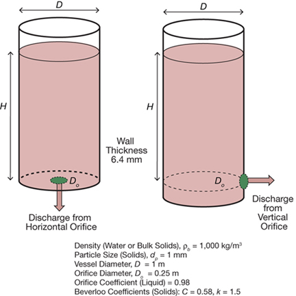
▲ Figure 1. Liquids and bulk solids discharge from a tank at different rates, which depend on different factors.
The classic example of discharge from a tank (Figure 1) illustrates the differences in discharge behavior of liquids vs. bulk solids. Consider two otherwise identical tanks, one with a horizontal orifice at the bottom and the other with a vertical orifice on the side near the bottom. To permit comparison of discharge rates through horizontal and vertical orifices, the center of the vertical orifice is located at the same height as the horizontal orifice; that way, the height of material above each tank’s outlet, or surcharge height (H), is the same. The tanks can be filled with liquid or bulk solids with equivalent density and filled to the same surcharge height. A comparison of the liquid and solids discharge rates shown in Table 2 reveals that:
- the discharge rate of solids depends on the orientation of the orifice and is independent of surcharge height
- the discharge rate of liquids depends on the surcharge height and is independent of orifice orientation
- the discharge rate of free-flowing solids is significantly lower than the discharge rate of a liquid of the same density.
| Table 2. Orifice orientation and surcharge height have different effects on the discharge rates of liquids and solids. | |||
| Orifice Orientation | Surcharge Height, m | Liquid Discharge Rate, kg/sec | Bulk Solids Discharge Rate, kg/sec |
| Horizontal | 2.5 | 336.9 | 55.9 |
| Horizontal | 5.0 | 476.5 | 55.9 |
| Vertical | 2.5* | 336.9 | 25.2 |
| Vertical | 5.0* | 476.5 | 25.2 |
| * Assumes the center of the vertical orifice is at the same height as the horizontal orifice. | |||
Understanding discharge flow patterns and rates
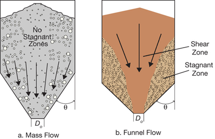
▲ Figure 2. Solids discharging from a hopper may exhibit mass flow, in which all of the solids are in motion (a), or funnel flow, which is characterized by a stagnant zone along the walls (b).
The flow pattern (velocity gradients and dead zones) and stresses within the bulk material during discharge from a silo, bin, or hopper depend on friction between the particles (internal friction), friction between the particles and the wall (wall friction), and the inclination of the converging section (hopper half-angle). Figure 2 illustrates the two main flow patterns: mass flow and funnel flow (2). Mass flow occurs when the cone is sufficiently smooth and/or steep to ensure particle movement along the wall. Funnel flow occurs in hoppers with a shallower cone angle, which allows a stagnant region to develop along the walls of the converging section and extend into the cylindrical section. Each of these flow regimes creates unique stress patterns and velocity gradients within the silo, so they must be treated differently.
Lacking a reliable theoretical framework, early researchers employed an empirical or semi-empirical approach to data analysis with a focus on free-flowing (noncohesive) incompressible solids. Agricultural products (e.g., grains, seeds) and ideal test materials (e.g., glass beads, lead shots) have commonly been used to develop correlations. A consensus on the pertinent factors affecting the discharge rate slowly emerged, and the key differences between discharge rate characteristics of granular solids and fluids through orifices or apertures — namely, the effect of surcharge height, orifice orientation, and orifice shape and size — were quantified and codified. The correlations revealed that the discharge rate of granular solids is:
- largely independent of surcharge height
- strongly influenced by the inclination of the orifice
- a function of the diameter of a circular orifice raised to the 5/2 power.
During the 1960s to 1980s, several new approaches (3–9) emerged, creating a theoretical framework for gravity flow of bulk solids from bins and hoppers. Although the mathematical details differ, the theoretical expressions were similar to accepted empirical formulations that delineate the effects of orifice diameter, bulk density, particle size, cone angle, internal friction, wall friction, and surcharge height on discharge rate. These theories qualitatively capture the relationships between influencing factors very well, but calibration might be required for quantitative predictions. Jenike (2) and Johanson (10) combined a continuum approach with principles of soil or powder mechanics to develop a complete framework for reliable flow of cohesive and compressible solids from bins and hoppers.
Discrete (or distinct) element modeling (DEM) has emerged as a viable computational tool to help in understanding the dynamics of flowing granular solids. As computational power has grown, so has our ability to model realistic systems with sufficient detail to quantitatively predict flow behavior in geometries that do not lend themselves to a simple analysis. These tools will continue to be refined and validated, and will enable the next phase of in silico research in solids handling.
Numerous factors influence the discharge rate of particulate solids:
- particle size — coarse vs. fine
- particle size distribution
- particle shape
- ratio of particle size to orifice diameter
- flow pattern — mass flow vs. funnel flow
- degree of cohesion — free-flowing vs. cohesive, angle of internal friction, electrostatics, moisture
- compressibility
- permeability and state of aeration (especially for fine powders)
- orifice orientation — horizontal, vertical, inclined
- orifice geometry — circular, slot, arbitrary shape
- vessel wall thickness (of inclined orifices)
- pressure drop across outlet — flow assist vs. flow impediment
- time consolidation (especially for fine powders)
- temperature.
One of the challenges engineers face when designing a solids handling system is the choice of equation or approach to take (or avoid) for evaluating discharge rates. Simple calculations are often sufficient for free-flowing, noncohesive, incompressible solids (e.g., polymer pellets, coarse grains). On the other hand, detailed two-phase analysis must be performed for fine powders (e.g., cement, flyash, fine coal), as oversimplification in the analysis of powder discharge rates may lead to flooding, erratic flow, or no flow (cohesive arching).
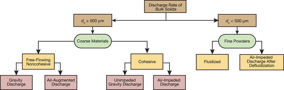
▲ Figure 3. Bulk solids may be classified as granular or coarse solids (dp ≥ 500 μm) or fine powders (dp < 500 μm).
Bulk solids can be classified into two broad categories based on differences in the underlying physics — granular or coarse solids (dp ≥ 500 μm) and powders (dp < 500 μm) (Figure 3). Particle size distribution also affects the bulk flow behavior of particulate solids. For instance, coarse materials with more than 25% of the particles smaller than 50 μm might exhibit flow behavior similar to that of fine powders.
COARSE SOLIDS, dp ≥ 500 µm
Gravity discharge of free-flowing (noncohesive) solids, such as dry sand or plastic pellets, out of a vessel is a common practice. The discharge rate is usually throttled by altering the opening of an orifice; the maximum discharge rate is obtained when the outlet is fully open. Applying varying levels of surcharge air pressure (i.e., additional pressure in the headspace, such as in a blow pot for dense-phase conveying) can further increase the discharge rate and provide additional control. To design and specify process equipment, we must therefore be able to quantify the effect of surcharge pressure on the discharge rate.
Gravity discharge through a horizontal orifice in a flat-bottom bin
The simplest scenario is the discharge of coarse, granular, noncohesive particles of uniform size flowing through a horizontal circular orifice.
The Beverloo Equation (11) is a simple expression for calculating the discharge rate (W) of solids from a flat-bottom bin through a horizontal circular orifice as a function of orifice diameter (Do):

where ρb is the bulk density of the solid, g is acceleration due to...
Would you like to access the complete CEP Article?
No problem. You just have to complete the following steps.
You have completed 0 of 2 steps.
-
Log in
You must be logged in to view this content. Log in now.
-
AIChE Membership
You must be an AIChE member to view this article. Join now.
Copyright Permissions
Would you like to reuse content from CEP Magazine? It’s easy to request permission to reuse content. Simply click here to connect instantly to licensing services, where you can choose from a list of options regarding how you would like to reuse the desired content and complete the transaction.